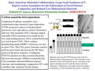
Flexible Carbon Nanotube Based Temperature Sensor for Ultra Small Site Application
Flexible Carbon Nanotube Based Temperature Sensor for Ultra Small Site Application. Capstone 2007 | Final Presentation. Brendan Crawford | Dan Esposito | Vishal Jain | David Pelletier Prof. Mavroidis | Prof. Jung | Dr. Khanicheh. Problem Statement .


Flexible Carbon Nanotube Based Temperature Sensor for Ultra Small Site Application
E N D
Presentation Transcript
Flexible Carbon Nanotube Based Temperature Sensor for Ultra Small Site Application Capstone 2007 | Final Presentation Brendan Crawford | Dan Esposito | Vishal Jain | David Pelletier Prof. Mavroidis | Prof. Jung | Dr. Khanicheh
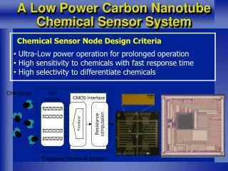
Problem Statement • To design and fabricate a novel thermal sensing device with nano-scale elements for ultra small site applications.
Needs Assessment • Based on interviews, research and industry needs, the prospective device should be have following capabilities • Higher spatial resolution • Volume manufacturing • Flexible • - Low power consuming • - High sensitivity • - Ease of integration • - Fast response time • - Bio compatibility
Applications Growing interest in flexible electronics Measurement of electrolyte temperature in polymer electrolyte fuel cell (PEFC) Precision cooling control for electronics Functionalized to work as small site chemical sensors In-vivo bio-medical applications Microfluidics Polymerase Chain Reaction (PCR) Temperature monitoring
Temperature Measuring Methods • Resistance Change (RTD) • Best overall performance range • Bimetallic Expansion • Limited sensitivity • Accuracy • Thermocouple • Limited sensitivity • SPR (Surface Plasmon Resonance) and other optical methods • Sensor must be exposed to light and measurement equipment • Infrared • Restricted to surface measurements
Carbon Nanotube Network Substrate Current (I) Metal Electrodes Voltage (V) CNT Network Expanding element CNT & Expanding element stretch ΔT x Substrate Metallic Nano Wire Metal electrodes Δx Substrate Current (I) Voltage (V) Concept Evolution
Literature Search Patent # 6905736: “Fabrication of Nano Scale Temperature Sensors and Heaters” Patent # 7194912 “Integrated Carbon Nanotube Sensor” Patent # 6905736 “Temperature Sensor Using Selective Lateral Growth of Carbon Nanotube Between Electrodes” 2005 5th IEEE Conference on Nanotechnology “Bulk Carbon Nanotube as Thermal Sensing and electronic Circuit Elements” 2004 4th IEEE Conference on Nanotechnology Patent # 7194912
Carbon Nanotube Advantages • Superior material properties compared to conventional materials • SWNT: ~ 1 nm diameter • Tensile Strength: ~1000 GPa • Tensile Elongation 20% • High mechanical strength • (100x stronger than steel) • - Thermal Conductivity . 1750-5800 W/m∙K) • - High current density (1000x higher than Cu) • - High electric conductivity: 10-4 ohm-cm (27°C) Source: www.applied-nanotech.com/cntproperties.htm
Design Concept with Dual Expanding Elements Encapsulated in Parylene C Electrode Expansion Elements CNT Network - Due to a change in temperature, shear in the expansion elements induces an amplified local strain in the CNT Network
Material and Dimension Selection • Design Requirements • Max stress in CNT Network < 30 MPa (elastic region) • Strain to be between 0.5% to 2% to induce reasonable change in resistance in the CNT network • Dimensions to be as small as possible • Expansion element • High thermal coefficient of expansion • Compatible for batch fabrication • Material Selection • Parylene • Bio compatible • Flexible • encapsulates CNT network from operating contamination • Polymethyl methacrylate (PMMA) • High thermal coefficient of expansion (3.5x greater than zinc) • Standard material used for CNT processing
Modeling Thermal-Structural Analysis • Loading Conditions: • Bottom (mounting) surface insulated • All other outer surfaces subjected to a maximum temperature change of 100 °C • Assumptions: • Electrodes not included in the model • Static analysis Mounting Surface
Thermal Structural Analysis Dimensional Analysis: • Dimensions of PMMA and the insulation of the CNT gap varied between 0.5um and 5um • Dimensions of CNT Network, Parylene C encapsulation (top and bottom) are fixed. To meet the design requirements, PMMA and Parylene C widths chosen to be 1um FEA results with both elements at 1um wide
Overall dimension of the sensing element 50um long x 24.5 wide x 20.5 height
Expanding Element vs. No Expanding Element • For the chosen device dimensions, the sensitivity of the device with an expanding element is predicted to be 16X more responsive than a device without it
Fabrication Process Deposit 10um of Parylene C on Si substrate Modify surface with O2 plasma Acetone Lift yielded defined CNT network 1 4 Titanium Electrodes deposited at ends of CNT network Nanoscale trench in PMMA via electron beam lithography (EBL) 5 2 EBL is used to selectively place PMMA on both sides of the network 6 SWNT Solution is drop cast at 10o angle 10um of Parylene C is deposited, the electrodes are exposed an the device is removed form the hard substrate ` 3 7 Silicon Substrate CNT Network Titanium Electrode Parylene C PMMA (expanding element
Prototype • Fabricated with optical lithography • Various masks, casting and lift off methods tested • Multiple trench contact - 3um widths x 9um spacing • Electrodes fabricated through Ti sputtering 20,000x 1000x 50x
Calibration & Testing • Make electrode contact using microprobes • Obtain I-V curve at room temperature to establish closed circuit • Vary sensor device temperature between 25 °C to 60 °C
Conclusion & Future Work • Conclusion • Successfully fabricated a Parylene encapsulated CNT based device • Calibrated the device to obtain the Resistance vs. Temperature curve • Provisional Patent disclosure applied for the “Dual Expanding Element” concept • Future Work • Manufacture the device with expanding element • Test the new device • Obtain the Frequency Response • Reliability/Repeatability Testing
Acknowledgements Our advisors: Constantinos Mavroidis, Azadeh Khanicheh, Yung Joon Jung Additional Thanks to:
Polymer Electrolyte Fuel Cell (PEFC) • Temperature measurement of electrolyte critical to operation of PEFC • Requirements: • resistance to tensile force • resistance to strongly acidic and electrochemical environment • Current method • Parylene encased MEMS thermistor • CNT based sensor • Flexible until 2% strain in CNT • Parylene film resist to chemicals • Higher spatial resolution than the MEMS thermistor • Faster response time
Basic Design Concept CNT Network Metal Electrodes Expanding Element Substrate • CNT network as resistive element • To increase sensitivity by inducing an resistance modifying force as a function of temperature • CNT dimensions in the nanoscale range (<100nm) Current (I) Voltage (V)
Previous study (Muftu et. al*) of a 20um Parylene film encapsulating CNT network showed following results • If strain < 2%, CNT network remains elastic • Change in resistance vs. strain (<2%) is linear *Solid State Sensors, Actuators and Microsystems Conference, 2007
PMMA & Parylene C Properties Parylene C PMMA