Download
1 / 16
160 likes | 179 Views
Learn about ANKA Vacuum System parameters, preparation, and maintenance for optimal performance. Understand the layout, pumps, absorbers, and precautions to prevent accidents. Stay informed on vacuum behaviors, recoveries, and necessary instrumentation.

E N D
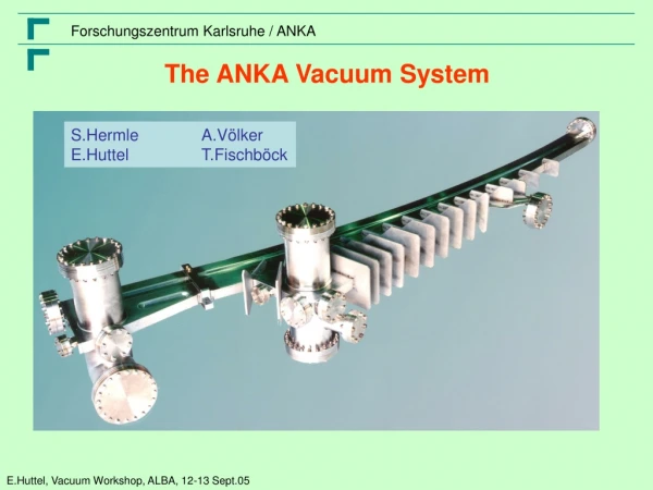
The ANKA Vacuum System S.Hermle A.Völker E.Huttel T.Fischböck
ANKA Parameter In operation: 3 Beam lines for Micro fabrication 9 Analytical Beam lines In planning: 3
One of the Row Ingmar Lehmann, FMB Lothar Schulz, SLS Erhard Huttel, ANKA
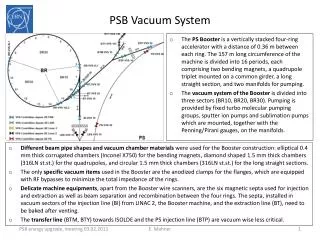
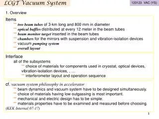
Lay out, Continued Large Chamber (Dipole plus following Quad /Sextupole ) e-beam Chamber plus Ante Chamber Each ante chamber: Lumped absorber (Covering 80% of SR) Large (500/300 l/s) pumps Following chamber: e-beam chamber only Distributed Absorber Small pumps (150 l/s) every 1.5 m
Pumping Standard Diode Ion pumps Varian 16 x 500 l/s 16 x 300 l/s 63 x 150 l/s 30 Controller 300 l/s + 500 l/s connected to 1 Contr. Up to 8 150 l/s connected to 1 Contr. Each pump current measured
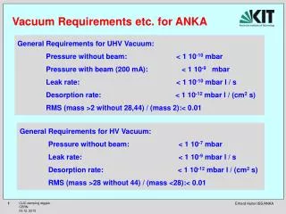
Vacuum Preparations and Assembling Specification: Leak rate < 10-10 mbar l/s Desorption rate: < 10-12 mbar l/ (s cm2) Masses>40 < 0.01 No Firing Baking and test at factory Baking and assembling on side (Pumps, gauges, absorber) Venting with N2 Assembling in storage ring Pumping
Expected Vacuum Behavior Lumped Absorber V.V.Anashin et al. EPAC(1998)2163 Distributed Absorber C.Herbeaux et al. Vac60(2001)113 Exposed: 0.035 m Factor 10 difference for dose per length 10 Ah 100 Ah
What We Get (Logarithmic Scale) ! Saturation due to Touscheck SLS Prediction PAC98 Linear in Energy and Current
What Happened (Linear scale) ! SCU14 Kr Accident SUL Wiggler With more Valves now, 10 Ah to recover when venting straight section only Wera Undulator + Broken Window 50 Ah to recover, when ¼ of storage ring vented N2 100 Ah, when vented with air
Major Accident I (Kr Lamp 2002) Syn.Rad. Kr lamp for baking behind Be – Mirror (Exposed to SR) Broke (Standard diodes do not pump noble gases) Pumped Storage Ring with Turbo Pumps While baking all Pumps Recovered!! Not my design!! They did not tell us! Look for the BL design!! Conclusion: Standard Diodes or ok
Major Accident II 2003 (Broken FE Window) Pyrex window in Diagnostic Front End Replaced after 3 Year of Use (became brown) New one broke after 6 month Syn.Rad. Exposed SR to air H2O !, Not dry N2 ! Cleaning with Syn.Rad. took 100 Ah to recover!
Instrumentation (Storage Ring) No Pirani, I do not miss them ! 12 Penning Gauges 4 QMS 95 Ion Pump Current Monitors