Download
1 / 8
80 likes | 219 Views
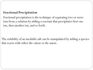
MIPA status report (Miniature Ion Precipitation Analyzer). David McCann, Swedish Institute of Space Physics, Kiruna, Sweden Prepared for GSST Workshop, Gothenburg 050912 ( david.mccann@irf.se ). MIPA basic features. Three major sub-units: 1. Electrostatic deflector

E N D
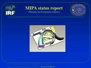
MIPA status report(Miniature Ion Precipitation Analyzer) David McCann, Swedish Institute of Space Physics, Kiruna, Sweden Prepared for GSST Workshop, Gothenburg 050912 (david.mccann@irf.se)
MIPA basic features Three major sub-units: 1. Electrostatic deflector 4. deflector high voltage plates 2. Electrostatic analyzer 5. analyzer high voltage plate 11. UV attenuation structure 3. time-of-flight unit 6. time-of-flight cell 7. start surface 8. stop surface 9. start ccem* 10. stop ccem* * Ceramic Channel Electron Multiplier
Status • A TM (Technological Model) of MIPA is fully integrated and set up for tests. • HV stability tests has been performed without encountering any problems. • A fully functional prototype of the HVPS has been integrated and will be used for calibration tests of the TM. • Layout of the time-of-flight electronics is on-going and will be concluded within the next few weeks. • A fully functional rough prototype has been integrated for use on the TM. • Thermal tests of the CCEM’s have been concluded. • Noise levels do not exceed acceptable levels.
MIPA TM Left: i. View of TM set-up in vacuum chamber at IRF. ii. The box under the sensor will be used for storing the hvps and time-of-flight electronics boards. Right: i. View of TM without sensor cover.
HVPS View of the HVPS. Dimensions: ~75g 120x60x30 mm
TOF electronics Picture of the time-of-flight electronics board (rough prototype) set up in the vacuum chamber at IRF. Dimensions (of flight board): ~80g 120x60x15 mm
UV trap • Left: • View of the base structure with deflector grid and UV rejection unit integrated. • Right: • Focused view of the UV rejection plates. • The unit comprise 14 blackened aluminum plates. Interplate spacing is ~0.2mm with plates roughly 0.1mm thick
Status comments MIPA is well on schedule. We will be able to conclude tests and calibration of the TM during oct/nov 2005. As of now, no critical action items are identified.