Semion System
Semion System. “. Retarding Field Ion Energy Analyzer. Importance of ion energy distribution (IED) measurements. Wafer processing controlled by energy and flux of bombarding ions e.g . etch rate, etched feature quality Ion energy measurement critical for process development

Semion System
E N D
Presentation Transcript
Semion System “ Retarding Field Ion Energy Analyzer
Importance of ion energy distribution (IED) measurements Wafer processing controlled by energy and flux of bombarding ions e.g. etch rate, etched feature quality Ion energy measurement critical for process development Wafer usually processed using RF excitation typically, 2-60MHz Difficult conditions in which to measure IED - electrical filtering, high temperatures, sensor etched or coated during processing RFEA sensor for IED measurements developed, easily incorporated into existing reactors, compatible with majority of substrate bias conditions
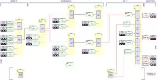
RFEA Schematic Plasma + - Aperture G1 Insulator Filter -60V G2 Filter 0 to +V G3 Filter -70V G4 Filter I -60V C
Nickel Grid Structure Electron microscope image of a nickel grid
IV Curve and Calculated IED Average ion energy Ion flux
Design considerations Orifice diameter < Debye length λD e.g. Te=3eV, Ne=1017m-3 …… λD~40µm Ion transit length < Ion mean free path λi RFEA depth 0.6mm ~ 100mTorr in Argon
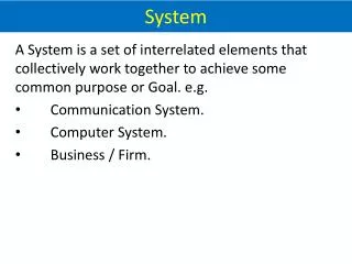
Installation Located at any location inside a plasma reactor Floating, RF bias, grounded Connected through a vaccum port via ceramic beaded cable Computer Semion Electronics Generator Match Plasma Reactor
IED • Shape of IED determined by sheath potential, ion transit time and period of sheath potential waveform. • For DC sheath, <E>~<Vs>, E~0 Plasma + - Aperture G1 Insulator Filter -60V G2 Filter 0 to +V G3 Filter -70V G4 Filter I -60V C
IED • For rf modulated sheath: • Ion transit time = Plasma + - Aperture G1 Insulator Filter -60V G2 Filter 0 to +V G3 Filter -70V G4 Filter I -60V C
Results DC Sheath - Pressure Computer Semion Electronics Generator Match Plasma Reactor
Results RF Sheath - Bias Computer Semion Electronics Generator Match Plasma Reactor
Results RF Sheath - Frequency Computer Semion Electronics Generator Match Plasma Reactor