Miniaturized Ion Trap Mass Analyzer for Trace Chemical Analysis in Various Industries
560 likes | 675 Views
The growing demand for detailed molecular information has spurred advancements in mass spectrometry, pivotal for analyzing compounds across biomedical, environmental, and law enforcement sectors. Traditional mass analyzers face challenges in size and cost due to complex electrode designs. Our innovative technology simplifies this by using a single voltage-dividing electrode that enables miniaturization and cost reduction. This novel design enhances performance, enabling rapid and precise detection of various substances, such as drugs and environmental contaminants, in real time.

Miniaturized Ion Trap Mass Analyzer for Trace Chemical Analysis in Various Industries
E N D
Presentation Transcript
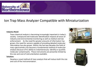
Ion Trap Mass Analyzer Compatible with Miniaturization Industry Need: Trace chemical analysis is becoming increasingly important in today’s society. Compound and molecular identification impacts all areas of industry and environmental monitoring as well as medical and law enforcement. As the need for greater amounts of information has grown, the need for sensors capable of providing detailed molecular information has also grown Within the last two decades the field of mass spectrometry has become a fundamental method of molecular analysis because of its ability to instantaneously identify or quantify molecular contaminants. These instruments are presently limited by the size and cost of instrumentation available. Solution: Develop a novel method of mass analysis that will reduce both the size and cost of the instrumentation.
Application Areas • Biomedical analysis • Hazard/explosive analysis • Environmental monitoring Examples: • Rapid analysis of patient profile in hospitals • Drug and metabolite monitoring • detection of explosives/accelerants • Detection of trace levels of pesticides and other contaminants in real time • Etc.
About The Technology Creation of the electric fields needed to trap and analyze molecules has always relied on producing uniquely shaped electrodes that will create the desired effect. These complex shaped electrodes are often both difficult and expensive to produce resulting in high cost and an inability to reduce the size. This dependence on shaped electrodes makes miniaturization increasingly difficult and therefore limits the range of implementation of the spectrometer. By varying the conductivity of the surface of the electrode, it is possible to use the single electrode as a voltage dividing device which alters the potential field generated by the ion guide at different locations.
Impact of the Technology Because the analyzer can be reduced to this dimension, it is possible to boost the performance of the analyzer by combining a large number of MPIG electrodes into a miniaturized array. This array type analyzer could be miniaturized using nano-technology reducing both the cost and size of the sensors • Development Stage: • Intellectual Property Status and Contact: • Provisional patent • Contact Ron Padavich, UNI Intellectual Property Officer • 319-273-6942 ronald.padavich@uni.edu
Electrode Array having a Thin Flexible SubstrateUIRF Ref. No. 00075 • Industry Need: Brain surface electrodes used in neurological studies and treatment, such as electrocorticography (ECoG), must be able to monitor and simulate neural activity with high spatial resolution. This requires high contact density (number of electrodes in a fixed area) as well as high signal to noise ratio. An array of micro sized electrodes is the ideal choice for neurological applications, but the potential use on human subjects is limited by the conventional materials and physical compatibility.
About the Technology Electrode Array having a Thin Flexible Substrate (UIRF 00075) • Researchers at the University of Iowa have developed a biocompatible electrode array that can be placed on brain surface of human and mammalian subjects. The array of micro-sized electrodes (less than 100 um in diameter and 10 um to 50 um in thickness) is fabricated on a thin film that is approximately 0.003 inches thick. All materials used are biocompatible and are suitable for mammalian subjects. The flexible substrate allows the electrode array to be configured to conform to the irregularly shaped surface of the brain without causing any damage to brain tissue. The microelectrode array and the thin film substrate combined provide improved contact density and spatial resolution that are crucial for the research in electrophysiology and neurology.
Benefits Electrode Array having a Thin Flexible Substrate (UIRF 00075) • MICRO ELECTRODE ARRAY ON BIOCOMPATIBLE SUBSTRATE • Micro-fabricated electrode array on biocompatible substrate allows safe electrophysiologic studies in humans and other mammals. The array of micro-sized electrodes also improves contact density which leads to higher spatial resolution. • FLEXIBLE SUBSTRATE • The substrate is a flexible thin film which allows the electrode array to establish continuous contact with the surface of the brain.
Status Electrode Array having a Thin Flexible Substrate (UIRF 00075) • Stage of Development: • Proof of Concept / Prototype • Feasibility has been demonstrated • Intellectual Property: • Issued US Patent 6,624,510 (9/23/2003 - active until 2020) More information: https://research.uiowa.edu/uirf/pages/technologies/k/07084/ Contact Information: Shannon Sheehan shannon-sheehan@uiowa.edu 319.335.4605
Optical Analyte Detection System UIRF Ref. No. 05043 Industry Need: The accurate, reproducible, real-time measurement of specific analytes present in biological fluids would provide physicians with the most-relevant and useful information on which to base treatment decisions. This type of analysis would prove particularly valuable for the measurement of glucose, important in diabetes maintenance, but could also be applied to other physiologically-relevant compounds, such as urea, lactate, triglycerides, cholesterol, etc. • Solution: A microspectrophotometer-based system for the efficient detection of specific analytes.
About the Technology Optical Analyte Detection System (UIRF 05043) • Researchers at the University of Iowa have developed a device for the accurate measurement of analytes in a biological or non-biological solution. • This device, which could be implanted, is an optical sampling cell that contains a electromagnetic radiation source and a microspectrometer. • The microspectrometer collects one or more parameters of the analyte in the infrared spectrum and reports the concentration data for this analyte in real-time. • Because this device uses light absorption data for the analyte, it requires no additional reagents for analyte determination and thus provides continuous data without any recycling of components. (U.S. Patent No. 8,204,565)
Benefits Optical Analyte Detection System (UIRF 05043) • REAGENTLESS. The optical-based measurement allows data to be gathered in the absence of additional reagents. This decreases the size and cost of the device and increases its useful life • CONTINUOUS MEASUREMENT. The data provided by this device is uninterrupted and updated immediately, providing the most relevant information of medical and other applications • IMPLANTABLE. This device is constructed in such a manner that its size and lifespan for effective measurement allow the device to be implanted in patients or situated in difficult to access industrial sites. In addition, the analyte information can be transferred wirelessly thus simplifying the data-gathering process • INFRARED ABSORPTION-BASED DETECTION. The measurement is based on infrared absorption spectra, which provide several absorption data points confirming the analyte-specificity of the signal
Status Optical Analyte Detection System (UIRF 05043) • Stage of Development: • Proof of concept / Prototype • Feasibility has been demonstrated • Intellectual Property: • U.S. Patent No. 8,204,565 (Issue Date: June 19, 2012) More information: https://research.uiowa.edu/uirf/pages/technologies/k/05043/ Contact Information: Catherine Koh catherine-koh@uiowa.edu 319.335.4659
Electronic Support System for Biological Data Sensor UIRF Ref. No. 05049 Industry Need: The accurate, reproducible, real-time measurement of specific analytes present in biological fluids would provide physicians with the most-relevant and useful information on which to base treatment decisions. This type of analysis would prove particularly valuable for the measurement of glucose, which is important in diabetes maintenance, but could also be applied to other physiologically-relevant compounds, such as urea, lactate, triglycerides, cholesterol, etc. Solution: This apparatus provides the necessary controls to allow a biological sensor to function while implanted in a patient.
About the Technology Electronic Support System for Biological Data Sensor (UIRF 05049) • Researchers at the University of Iowa have created an electronic support system that is capable of controlling an implanted biological data sensor. • This system consists of: • Central controller • Data acquisition unit • Telemetry unit • Rechargeable power unit (US Patent Application Serial No. 11/348,615)
About the Technology Electronic Support System for Biological Data Sensor (UIRF 05049) • This system is capable of providing the control required to organize the acquisition of biological sensor data, as well as the proper metered therapeutic response (e.g., insulin for diabetes patients) • The integration of these features also allows the device to be implanted and inaccessible for periods of time without interfering with the functionality of the device. (US Patent Application Serial No. 11/348,615)
Benefits Electronic Support System for Biological Data Sensor (UIRF 05049) • REMOTE DATA ACQUISITION AND TRANSMISSION. This control system coordinates the collection of analyte sensor data, such as infrared based spectrum information, and relays it wirelessly to a remote site. This provides for continuous, real-time data acquisition • REMOTE BATTERY CHARGING. The ability to charge wirelessly is essential to allow for full implantation of the device for ease of patient use and increased compliance • INTEGRATED CONTROL. Integration of control of the electromagnetic source, the sample collection, the method of detection as well as the therapeutic closed-loop response makes this a self-sufficient device
Status Electronic Support System for Biological Data Sensor (UIRF 05049) • Stage of Development: • Proof of concept / Prototype • Feasibility has been demonstrated • Intellectual Property: • US Patent Application No. 11/348,615 (Filing Date: February 7, 2006) More information: https://research.uiowa.edu/uirf/pages/technologies/k/05049/ Contact Information: Catherine Koh catherine-koh@uiowa.edu 319.335.4659
Dental Sculpting Brush UIRF Ref. No. 07084 Industry Need: Proper placement and shaping of composite resin (filling) constitute essential part of restorative dental treatment. Currently available composite sculpting brushes have straight handles and/or curved brush head with a fixed angle, hence hindering adequate access to every tooth surface, especially the ones in difficult to reach areas of the mouth. Solution: An experienced dentist at U. Iowa College of Dentistry developed a new design for dental composite sculpting brush having two angled heads and multi-directional brush head tip to which interchangeable brush tips are attached. Figures: http://www.cosmedent.com/products/composite-brushes/
About the Technology Dental Sculpting Brush (UIRF 07084) Two heads with most commonly used angles in dental hand instruments Larger diameter for comfortable handling and manipulation Durable materials that can withstand high temperature sterilization Multi-orientation Tip Different size, shape, and type of removable brush US 2011/0061190 (Application Serial No. 12/918,645)
Benefits Dental Sculpting Brush (UIRF 07084) • Provides greater access to obstructed areas such as lingual (the tongue side), gingival (gum line), spaces between teeth (embrasure space), and chewing surfaces (occlusal surface) of the molars • Stainless steel or anodized aluminum handle can be sterilized at high temperature (autoclaved – more cost efficient than low temp gas sterilization) and reused while brush tips can be replaced as needed • Single hand instrument with two different sizes/types of brush increases operative efficiency US 2011/0061190 (Application Serial No. 12/918,645)
Status Dental Sculpting Brush (UIRF 07084) • Stage of Development: • Proof of concept / Prototype • Feasibility has been demonstrated • Intellectual Property: • US Patent Application 12/918,645 (filed 11/22/2010) • PCT/US2009/001078 (filed 2/20/2009) More information: https://research.uiowa.edu/uirf/pages/technologies/k/07084/ Contact Information: Sean Kim hyeon-kim@uiowa.edu 319.335.4607
Arytenoid Repositioning Device UIRF Ref. No. 09025 Challenges in Arytenoid Adduction & Abduction: • Surgical procedure for treating laryngeal paralysis (unilateral- and bilateral- respectively) • Require extensive dissection of the neck of a patient under general anesthesia • Involves highly sophisticated placement of suture to secure the vocal cord in a functional position • Require extensive open surgeries when subsequent repositioning is needed Solution: • A small coiled titanium implant that can easily manipulate and secure the position of arytenoid and vocal cord Figure: Operative Techniques in Otolaryngology, 2012, 23, 178
About the Technology Arytenoid Repositioning Device (UIRF 09025) ARD is delivered to the position through a trocar Arytenoid Muscles Vocal Cord CT image of human cadaveric larynx with ARD in place and secured with hemoclips ARD Thyroid cartilage
Benefits Arytenoid Repositioning Device (UIRF 09025) • Smaller incision (~2 cm vs. ~6 cm), hence less invasive • Deep dissection of the neck is not necessary • Under local anesthesia when a fiberoptic trans-nasal laryngoscopy is used • Greater precision in positioning and securing arytenoid in the appropriate position • Repositioning, reversal, or removal can be done simply by clockwise or counter-clockwise rotation of the implant
Status Arytenoid Repositioning Device (UIRF 09025) • Stage of Development: • Proof of concept / Prototype • Feasibility has been demonstrated by cadaver studies • Animal studies in progress • Intellectual Property: • US Patent Application 13/201,669 (filed 8/16/2011) • PCT/US2010/27995 (filed 3/19/2010) More information: https://research.uiowa.edu/uirf/pages/technologies/k/09025/ Contact Information: Sean Kim hyeon-kim@uiowa.edu 319.335.4607
Surgical Pressurization Device UIRF Ref. No. 10070 Existing Limitation: During open heart surgery, steps must be taken to maintain the consistency of blood-gases and measure the integrity of the heart valves. Currently this is accomplished by flooding the surgical field with CO2to aid in blood-gas stabilization and repeatedly irrigating and aspirating saline to test for valve leaks. This method passively supplies CO2and therefore, may not provide the proper balance of gases required during surgery. In addition, non-pressurized monitoring of heart chamber valve integrity may not be sufficient for the identification of valve issues leading to inferior patient recovery. Solution: This medical device delivers pressurized CO2and irrigation fluid to the chambers of the heart during surgical procedures.
About the Technology Surgical Pressurization Device (UIRF 10070) • Researchers at the University of Iowa have developed a medical device for use during open heart surgery. This device is able to maintain desired blood-gas exchange in the heart and provide improve irrigation and valve leak detection during surgery. • This device injects CO2 and irrigation fluid into the heart chamber during surgery in a pressurized manner. The active delivery of CO2 improves blood-gas transfer over conventional passive methods of CO2 delivery, resulting in improved bloodstream CO2 concentrations during surgery. • In addition, the co-delivery of irrigation fluid to the site improves valve leak detection due to its pressurized and continuous delivery. The optimization of these two functions in one device simplifies and regulates the application of these important functions and results in improved patient recovery.
About the Technology Surgical Pressurization Device (UIRF 10070) (Patent Application No. PCT/US2011/062880)
Benefits Surgical Pressurization Device (UIRF 10070) • IMPROVED DELIVERY OF CO2. This system delivers CO2 in a pressurized format assuring the necessary transfer of CO2 into the bloodstream • DYNAMIC AND CONSTANT VALVE LEAK DETECTION. The pressurized addition of irrigation fluid provides a continuous and more complete option for valve leak detection over conventional bulb irrigation methods • SIMPLIFIED DELIVERY. This system and device is capable of optimally delivering pressurized CO2 and irrigation fluid to the heart chamber, improving surgical efficiency and patient recovery
Status Surgical Pressurization Device (UIRF 10070) • Stage of Development: • Proof of concept / Prototype • Feasibility has been demonstrated by the inventor • Intellectual Property: • Patent Application No. PCT/US2011/062880 (Filed: 12/1/2011) More information: https://research.uiowa.edu/uirf/pages/technologies/k/10070/ Contact Information: Catherine Koh catherine-koh@uiowa.edu 319.335.4659
Intensity Modulated BrachytherapyUIRF Ref. No. 11015 Background: Temporary brachytherapy is a relatively recently developed technique for delivering radiation therapy in specified quanta to a specific physiological region of the patient. This procedure uses a high-dose-rate (HDR) source to deliver radiation into a patient's tumor through thin needles guided by a computer-controlled afterloader. At the conclusion of each treatment, the radiation source is removed from the patient and no radiation is retained in the body. Temporary brachytherapy can be applied to a range of cancer types with initial studies focusing on the treatment of prostate, breast and cervical cancers.
Intensity Modulated BrachytherapyUIRF Ref. No. 11015 Existing Limitations: Conventional temporary brachytherapy treatments risk increased damage to surrounding normal tissue when they attempt to treat all tumor tissue present, because the zone of treatment is a uniform oval shape around the HDR source. • Solution: Spatially modulating the delivery of brachytherapy for each individual patient allows for greater dosing and less normal tissue destruction.
About the TechnologyIntensity Modulated Brachytherapy (UIRF 11015) Researchers at the University of Iowa have created a system for modulating the intensity of temporary brachytherapy to more completely treat the asymmetrical 3D shape of tumors. In order to more completely and safely treat the area covered by the irregularly-shaped tumor mass, the inventors have developed a device and method for introducing a compensator shield that releases only the radiation in the area of the tumor growth, while blocking any radiation release that would harm the surrounding normal tissue. This enables the physician to treat the entire tumor with high-dose radiation, increasing the chances for a favorable post-treatment prognosis for the patient. Figure (a) – A Compensator Prototype
BenefitsIntensity Modulated Brachytherapy (UIRF 11015) • CUSTOMIZED INTENSITY MODULATION • Radiation intensity is compensator-modified to place high intensity radiation in the region of the tumor only, regardless of its 3D shape • This modulation is specific for each patient, and allows for: • Customized intensity modulation • Asymmetric radiation dosing to match tumor symmetry • High intensity radiation treatment of tumor tissue • Limited damage to surrounding normal tissue • Reduction in delivery times of radiation dosing compared to conventional fan-based dosing. (Patent Application No. PCT/US2012/036979)
StatusIntensity Modulated Brachytherapy (UIRF 11015) • Stage of Development: • Proof of concept / Prototype • Feasibility has been demonstrated by the inventor • Intellectual Property: • Patent Application No. PCT/US2012/036979 (Filed: May 8, 2012) More information: https://research.uiowa.edu/uirf/pages/technologies/k/11015/ Contact Information: Catherine Koh catherine-koh@uiowa.edu 319.335.4659
Cellulose Based Heart Valve ProsthesisUIRF Ref. No. 11057 Background: The aortic heart valve separates the blood in the left ventricle from the blood in the aorta. This area of high pressure in the heart can expose defects in the aortic heart valve as patient's age, which necessitates replacements of the valve. Candidates for this type of procedure suffer from aortic stenosis (failure of valve to open fully) and/or aortic insufficiency/regurgitation (failure to prevent retrograde blood flow).
Cellulose Based Heart Valve ProsthesisUIRF Ref. No. 11057 Existing Challenges: Conventional treatment for these patients requires open heart surgery, a risk-laden procedure. New surgical procedures allow for delivery of such devices through needle holes (percutaneous delivery) instead of open incisions, decreasing procedure risk and patient recovery time. The properties desired for the prostheses used in this procedure include biocompatibility, durability, consistency and ease of delivery. • Solution: A collapsible aortic valve prosthesis incorporates a novel design to ease percutaneous delivery.
About the Technology Cellulose Based Heart Valve Prosthesis (UIRF 11057) Researchers at the University of Iowa have developed a novel heart valve prosthesis designed for use in the aortic valve. This device is collapsible, which allows it to be delivered by the surgeon percutaneously (e.g., through a leg vein). This delivery method is favored because it utilizes a needle based insertion method and avoids the more invasive incision-based method. The construction of this device consists of a stainless steel or nitinolframe, overmolded with a methylol cellulose-silicone composite. The cellulose based composite also forms the tricuspid valve structure associated with the aortic valve. The overmoldingproduction process creates a device that does not require the use of sutures during placement in the patient. The elimination of sutures decreases the risk of calcification of the valve over time, which is a primary mechanism responsible for the destruction of conventional valves that have been inserted for this purpose.
Benefits Cellulose Based Heart Valve Prosthesis(UIRF 11057) • CELLULOSE-BASED CONSTRUCTION. Cellulose is an abundantly available, naturally occurring, biostable polymer. Prostheses constructed of cellulose are inherently biocompatible, and can be collapsed during delivery of the device. In addition, the properties of cellulose (porosity, moldability, hemodynamic properties, etc.) can be modified to optimize the material for the aortic valve application. For example, it can be molded into any desired morphology, and its material chemistry and surface properties can be manipulated as well. • OVERMOLDING PRODUCTION METHOD. The process of molding the cellulose composite around the stent frame eliminates the requirement for sutures. This likely reduces stress points common with sutures. • NO GLUTARALDEHYDE FIXATION (as would be required with bovine or porcine valves). This potentially reduces the risk of calcification. Calcification is a primary cause of prosthesis failure for conventional devices. • COLLAPSIBLE DEVICE. The device is constructed to fold upon itself to allow for percutaneous delivery, which decreases patient risk and increases rate of recovery.
Status Cellulose Based Heart Valve Prosthesis (UIRF 11057) • Stage of Development: • Proof of Concept / Prototype • Feasibility has been demonstrated by the inventor • Mechanical testing (stiffness, strength) of prosthetic material • Assessment of long-term membrane (geometric) stability • Catheter crimping and deployment testing of assembled valve • Flow Testing of Assembled Valve in a pulse duplicator • Intellectual Property: • US Patent Application No. 61/597,330. (Filed: February 10, 2012) More information: https://research.uiowa.edu/uirf/pages/technologies/k/11057/ Contact Information: Catherine Koh catherine-koh@uiowa.edu 319.335.4659
In-device Controller for Endoscopic LensesUIRF Ref. No. 12024 Background: Current arthroscopes require two hands to operate - one to hold the camera, and another to rotate the viewport using the light post as a handle.
In-device Controller for Endoscopic LensesUIRF Ref. No. 12024 Existing Limitations: This is a problem during surgery, because the surgeon’s second hand is often using another tool, such as a blunt probe, spinning burr, or shaver. Currently, surgeons compensate for this by using an assistant, or tolerating a sub-optimal view until they can remove the other tool and return both hands to the arthroscope. Solution: The University of Iowa team has created an elegant solution by designing an arthroscope that has a viewport, which is easily adjustable using a simple thumb control, and thus facilitates single-handed operation.
About the Technology In-device Controller for Endoscopic Lenses (UIRF 12024) The University of Iowa team has created an elegant solution for freeing up the surgeon's hands, by designing an arthroscope that has a viewport, which is easily adjustable using a simple thumb control, and thus facilitates single-handed operation. Shown here, is an ergonomic arthroscope handle that integrates a camera, a small microprocessor controlled servomotor, and a thumb joystick to determine the position of the angle of an arthroscope lens. The lens can be rotated clockwise or counter-clockwise via the rotating device, which frees the user from rotating it manually. This design will give physicians more freedom by giving them more functionality for one of their hands. (Patent Application No. 61/661,657)
Benefits In-device Controller for Endoscopic Lenses (UIRF 12024) • The functionality of this device allows the surgeon to rotate the field of view provided by the endoscope 360 degrees, providing a consistently upright field of view. • IMPROVED VISUAL IMAGE. This device quickly orients the televised field of view to that which is desired by the physician. • EASE OF MANIPULATION. During these procedures, the practitioner is often asked to perform more manipulations than s/he can physically handle. The easily manipulated integrated controls of this device, allow the user to rotate the camera without the [extra] physical manipulation that is required in the currently existing system.
Status In-device Controller for Endoscopic Lenses (UIRF 12024) • Stage of Development: • Proof of concept / Prototype • Feasibility has been demonstrated by the inventor • Intellectual Property: • Patent Application No. 61/661,657. (Filed: June 19, 2012) More information: https://research.uiowa.edu/uirf/pages/technologies/k/12024/ Contact Information: Catherine Koh catherine-koh@uiowa.edu 319.335.4659
UIRF Available Technologies Website Contacts: Zev Sunleaf, Executive Director (zev-sunleaf@uiowa.edu) Shannon Sheehan, Licensing Manager (shannon-sheehan@uiowa.edu) Catherine Koh, Licensing Manager (catherine-koh@uiowa.edu) Sean Kim, Licensing Manager (hyeon-kim@uiowa.edu) https://research.uiowa.edu/uirf/index.html • Browse University of Iowa technologies available for licensing https://research.uiowa.edu/uirf/pages/technologies/ • Search by keyword, inventor, and category • Register to receive email alerts • https://research.uiowa.edu/uirf/pages/technologies/myaccount/register.php
Dual-Color Auto-Calibration Scanning-Angle Evanescent Field Microscope Industry Need Total internal reflection fluorescent microscopy (TIRFM) is a widely used method for imaging single molecule fluorescence at surfaces and interfaces. However, there is need for simpler and less time-consuming calibration methods for TIRFM. Solution An innovative dual-color auto-calibration scanning-angle evanescent field microscope that is easier to operate and more reproducible than existing approaches. Microscope for Live Cell Imaging: Licensing/Commercialization Opportunity
About the Technology • Permits high axial resolution (5-10 nm) • Provides quick and automatic creation of an evanescent field for any incident angle in the full range • Enables dual-color auto-calibration and scanning capability • Quickly scans through a set of samples • Allows rapid re-calibration of new samples • Enables fine adjustment of the optical trapping forces created by the evanescent field Microscope for Live Cell Imaging: Licensing/Commercialization Opportunity
Application Areas • Chemical and Biological Imaging • Live-cell imaging • Biophotonics • Imaging of complex interfaces Microscope for Live Cell Imaging: Licensing/Commercialization Opportunity
Status • Development Stage • The new microscope with an automatic high-precision calibration procedure has been tested under laboratory conditions and is available for demonstration. • Intellectual Property • ISURF #3750 • Patent pending Contact Information: Dario Valenzuela dariov@iastate.edu 515-294-4470 http://www.techtransfer.iastate.edu Microscope for Live Cell Imaging: Licensing/Commercialization Opportunity