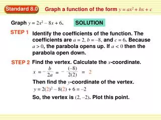
Download
1 / 54
540 likes | 647 Views
Learn about Geometric and Logical Networks, Network Flow, Weights, Solvers, and Two Views of Networks in ArcInfo 8.0 for efficient network data modeling and analysis. Understand the relationship between the two views for improved database design and analysis.

E N D
Topics • Network Data Model • Network Flow • Weights • Solvers
Network data model • Geometric and Logical views • Geometric and Logical Networks • Edge and junction features and elements • Simple edges • Complex edges and junctions
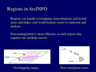
Two Views of Networks Geometry and Connectivity
Geometric and Logical Networks • The Geographic view is implemented as a Geometric Network • a collection of feature classes in a feature dataset • The Logical view is implemented as a Logical Network • a specialized data structure for storing connectivity
Understanding the relationship • Understanding the correspondence between the geometric and logical network is very helpful • Developers writing analysis programs deal almost exclusively with the Logical Network • Database designers, data builders, and analysts can all benefit from an understanding of this correspondence
Geometric Networks • Binds together feature classes that make up a network • Edge and Junction Features • Contains all network validation rules, relationships, attributes • Used for display and editing • Easily created with a wizard
Geometric Networks Network Feature Classes Valve Meter Lateral Geometric Network DistMain TransMain
Logical Networks • Store network connectivity • Maintained by Geometric Network • Behind the scenes - not shown in ArcCatalog • Network analysis programs use logical networks • Very high performance engine
Always maintained • The Geometric and Logical networks are always “in sync”, always “live” • No separate building and maintaining of network • Geometric Network maintains Logical Network • Smart network features
The centerpiece of a logical network is the connectivity table
Simple Network Features • One-to-one correspondence between features and elements
Simple Network Features • Single main servicing two houses • Connecting two simple junctions to simple edge results in three simple edges • one-to-one mapping
Complex Edges • One-to-many mapping between feature and edge elements • Connecting junction does not cause split • Complex edge may only be split with Split tool
Complex Edges • Note one-to-many feature to edge element mapping using Sub-ID
Complex Junctions • Single feature that is mapped to any number of edge and junction elements • Fixed topology • Utilizes connection points for establishing connectivity • Switchgear example
Complex Junctions • In this example, the switchgear is modeled as • four edge elements • five junction elements
Network Flow • Operational context • Establish Flow Direction • Flow direction part of Logical Network • Sources, Sinks, enabled/disabled state • Indeterminate and Uninitialized flow
Two operational contexts • In a street network, the commodities (automobiles) that flow through a network have a “will of their own”, and decide how they’ll flow through the network. • In a utility network, the commodities (water, electricity) have no will of their own, and the network imposes a flow direction.
Street and Utility Networks • Street networks have non-directed flow • Utility networks have directed flow
Establishing Flow Direction • A Utility network has an Establish Flow Direction Method, which determines the direction of flow along each edge element • Flow direction stored with Logical Network
Sources and Sinks • The Establish Flow Direction method uses sources and sinks • Sources and sinks are stored with the logical network • Implemented with Attribute Domains on Geometric Network
Enabled/Disabled state • Every element has an enabled/disabled state. • Implemented with attribute domains on Geometric Network. • The state found on features applies to all elements. You cannot turn off a portion of a complex edge.
Indeterminate Flow • It may not be possible to establish flow direction, typically due to cycles
Uninitialized flow • A network may have disconnected components - sets of elements that don’t connect to other sets • When a component cannot be reached by any source or sink, its flow is uninitialized
Weights • Features and elements can have any number of weights • Editing weight values in a network feature class table automatically updates the logical network
Weights • Weights on different classes can be mapped to single weight in logical network
Bitgate Weight • Used for categories • In this example, categories of vehicles are represented
Creating Geometric Networks • May use ArcCatalog or ArcToolbox • Use the New Geometric Network tool in the context menu • only on a feature dataset
Building Geometric Networks • Use wizard to specify • input feature classes • complex edges • snapping • ancillary roles • weights
Network Feature Classes • May add new feature classes to existing network • Use the New Feature Class tool in the context menu
Network Feature Classes • Choose a network feature type • ESRI Simple Junction • ESRI Simple Edge • ESRI Complex Edge • Custom • Choose network • Specify ancillary role
Network Analysis • Solvers • Flags • Barriers • Trace Solvers • Demos
Solvers • Solvers are programs that use a logical network to solve a problem • Numerous network problems = numerous solvers • Our strategy is to provide a rich suite of solvers that address the more common types of problems • Extensible environment to plug in solvers
Example solver written in Visual Basic • Implements a TraceTask solver • Plugs into ArcMap’s Utility Network Analysis Toolbar Implements ITraceTask . . .Private Function ITraceTask_OnTraceExecution() As esriCore.IEnumNetEID 'Check to make sure we have an edge flag set Dim m_pFlags As IFlagsAndBarriers Set m_pFlags = m_pTraceSolver If m_pFlags.EdgeFlagCount = 0 Then MsgBox "Set an edge flag before using this trace task" Set ITraceTask_OnTraceExecution = Nothing Exit Function End If 'Prepare for the trace Dim m_pNewTrace As ITraceFlowSolver Set m_pNewTrace = UTIL_CoreTraceSetup(m_pFlags) 'Make sure the solver came back If m_pNewTrace Is Nothing Then Set ITraceTask_OnTraceExecution = Nothing Exit Function End If 'Set the isolation layer Dim lIsolationFCID As Long Dim m_pTraceProperties As ITraceProperties Set m_pTraceProperties = m_pTraceSolver If m_pTraceProperties.IsolationLayerCount = 1 Then Dim iLoop As Integer lIsolationFCID = m_pTraceProperties.IsolationLayerFCID(CLng(iLoop)) For iLoop = 0 To m_pTraceProperties.IsolationLayerCount - 1 m_pNewTrace.DisableElementClass lIsolationFCID Next iLoop . .
Solver Interfaces • Collections of solvers that perform similar tasks can usually be plugged into a common user interface framework • A toolbar for solving water network problems, one for telco, one for routing, etc. • ArcMap is part of a solver user interface • Similarly, collections can implement similar behavior • Support common program interface (I.e., ITraceTask)
Solver inputs • Logical Network • Netflags • Barriers • Other parameters • weights
Solver Outputs • Collections of edge and junction elements • Netflag collections • Other stuff • numbers, booleans
Solver Renderers • Take solver output and displays in ArcMap • Converts element class ID, feature ID, and Sub-ID into geometry to display
Barriers • Used to temporarily disable elements • Four ways to specify barriers • Simple barriers - a collection of junction and edge elements • Selected sets of features • Feature class • Bitgates
Utility Network Analysis Toolbar • ArcMap Tool, accessed through the tool menu • Used to Establish Flow Direction and to perform Trace tasks • Six solvers • Three need to have flow direction established