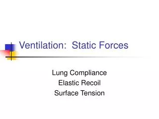
Static Machine Forces
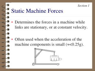
Section 1. Static Machine Forces. Determines the forces in a machine while links are stationary, or at constant velocity. Often used when the acceleration of the machine components is small ( < 0.25g). F = 100 lbs 30 0. Forces. Push or pull action. Vector quantity. Magnitude Direction

Static Machine Forces
E N D
Presentation Transcript
Section 1 Static Machine Forces • Determines the forces in a machine while links are stationary, or at constant velocity. • Often used when the acceleration of the machine components is small (<0.25g).
F = 100 lbs 300 Forces • Push or pull action. • Vector quantity. • Magnitude • Direction • Point of application
Force Components • It is often convenient to resolve a force into orthogonal components. • Use right triangle to determine the components • F1=F sinf • F2=F cosf F2 F1 f 2 1 F
d F A Moments • Twisting action produced by a force. • Computed relative to a point. • MA=F d • F = Force • A = Reference point • d = perpendicular distance between force and reference point. • Vector • MA = 250 in lbs, cw
Problem 1-2 A force is applied to a box wrench as shown. Determine the moment, relative to the center of the nut, when f = 300, and b = 700. b 25 lb 8 in. f
b 60 lb 12 in 18 in Problem 1-4 A force is applied to the control lever as shown. Determine the moment, relative to the pivot block, when b = 300.
Free-Body Diagrams • Isolate the component(s) that must be studied. • Draw the component as if it were floating freely. • Replace all supports with the appropriate force and/or couples (moments).
FBD Entire engine hoist E D F E D F 250 lbs C C Bx A B Ay By Free-Body Diagrams
FBD Link DEF D E Dx F Dy CE 250 lbs FBD Base Dy FBD Cylinder CE CE Dx D CE C CE Bx Ay Free-Body Diagrams By
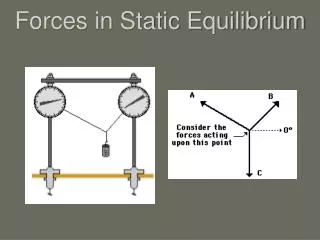
F Reaction Forces • As a general rule, if the nature of the contact prevents motion in a certain direction, there must be a supporting force in that direction.
Two-Force Members • A component that is acted upon by only two forces is known as a two-force member. • A two force member will always be in either tension or compression.
10 lbs 1.25 in 3.75 in Problem 1-12 Draw free-body diagrams of the links for the pliers when 10 lbs is applied to the handles
80” 18” 6” 18” 24” 24” 24” 10” Problem 1-13 Draw free body diagrams of all the components for the lift. The weight of the crate and platform are 1200 lb and 400 lbs. The weight of all other links is considered insignificant
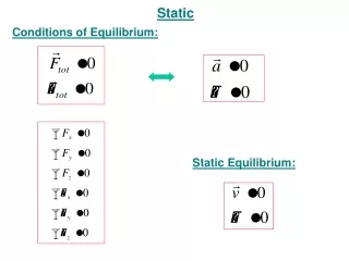
Static Equilibrium • A machine component is in static equilibrium when the combination of all forces is zero. • In addition, the net effect of all moments, about any arbitrary point, must also result in zero. SFx = 0 SFy = 0 SMi = 0
Hints to Solve Statics Problems • Draw free-body diagrams large and properly labeled all forces. • Identify any two-force members that are contained in the machine. • The shortest method of solution occurs when the first FBD incorporates both given information and what is required. However, a free body diagram can, at most, be used to determine three unknown forces.
Hints (con’t) • If the first FBD fails to give a full solution, draw several other free-body diagrams. Each additional FBD generates three additional independent equations. However it may generate additional unknown forces. Keep track of the total number of unknown forces and independent equations. • A FBD of the entire machine may be useful. • Remember that internal forces between connecting components are equal and opposite.
10 lbs 1.25 in 3.75 in Problem 1-12 Determine the force onto the nut when 10 lbs is applied to the handles of the pliers.
2 in 5 in 5 in 3 in 1500 lb 2 in 4 in Problem 1-14 The clamp has a rated load of 1500 lb. Determine the compressive force this creates in the threaded rod, AB
80” 18” 6” 18” 24” 24” 24” 10” Problem 1-13 Determine the cylinder force to maintain the position of the lift. The weight of the crate and platform are 1200 lb and 400 lbs. The weight of all other links is considered insignificant 45”
500 lb 24” 20.6” 16” 37.90 28” 75.60 30” 28” 37.90 12.9” 10” 36” 36” Problem 1-25 Determine the force from the hydraulic cylinder to keep the platform in the position shown.
5 m 2.4 m 1200 N 2.0 m 0.9 m 1.2 m Problem 1-16 Determine the force required by the hydraulic cylinder to maintain position of the bucket.