Download
1 / 26
260 likes | 419 Views
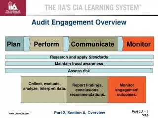
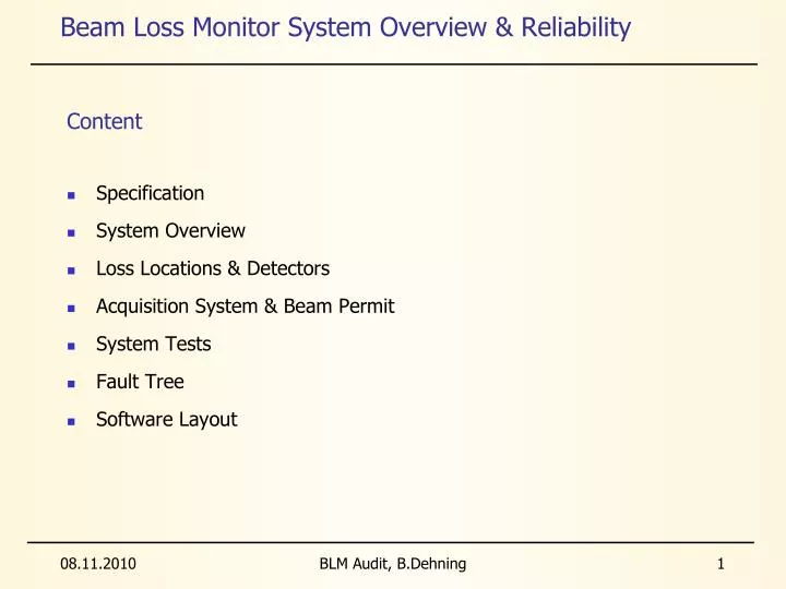
Beam Loss Monitor System Overview & Reliability. Content. Specification System Overview Loss Locations & Detectors Acquisition System & Beam Permit System Tests Fault Tree Software Layout. Beam Loss Monitor Specification. 5. USE OF THE BLM’S FOR MACHINE PROTECTION

E N D
Beam Loss Monitor System Overview & Reliability Content • Specification • System Overview • Loss Locations & Detectors • Acquisition System & Beam Permit • System Tests • Fault Tree • Software Layout BLM Audit, B.Dehning
Beam Loss Monitor Specification 5. USE OF THE BLM’S FOR MACHINE PROTECTION The strategy for machine protection impacts on the BLM design in two ways, its time response and the reliability. Protection of the machine from beam losses has two aspects: • protectionagainst beam losses that could lead to damage of equipment, • protection against beam losses that could lead to a quench of a magnet. Since a repair of superconducting magnets would take several weeks, the protection against damage has highest priority and damages should be strictly avoided (SIL 3, 1E-8 to 1E-7 1/h). In case of a quench, the quench protection system would prevent equipment damage. However, the beam would be lost and re-establishing operation would take several hours. Therefore the number of quenches should be minimized BLM Audit, B.Dehning
Loss Levels and Required Accuracy Functional specification:https://edms.cern.ch/file/328146/2.0/LHC-BLM-ES-0001-20-00.pdf BLM Audit, B.Dehning
Quench and Damage Levels • Detection of shower particles outside the cryostat or near the collimators to determine the coil temperature increase due to particle losses Quench level and observation range 450 GeV 7 TeV Damage levels Dynamic Arc: 108 Time resolution1/2 turn BLM Audit, B.Dehning
BLM Aims • Monitor the 27 km of accelerator to detect dangerous losses. • Trigger beam extraction requests to avoid damages of the superconductive magnets and of other equipments. The BLMS must be : • 1. SAFE: in case of dangerous loss, it has to inhibit the beam permit. If it fails, there will be ~30 days of downtime. • 2. FUNCTIONAL:in case of NO dangerous loss, it has NOT to inhibit the beam. If it fails, it generates a false alarm and 3 h will be lost to recover the previous situation. Such an event will decrease the LHC efficiency. BLM Audit, B.Dehning
Location of Detectors • Distinguish between beams • Observe losses due to magnet misalignments • Observe losses due to orbit changes and emittance growth Every dangerous loss could be seen just by one detector. Impact of protons in the centre of the quad. magnet BLM Audit, B.Dehning
BLM Signal Chain Beam Loss Monitors (4000) Acquisition Cards (700) Tunnel Optical fibres Surface around the LHC ring BLM Audit, B.Dehning
Ionisation Chamber and Secondary Emission Monitor • Stainless steal cylinder • Parallel electrodes distance 0.5 cm • Diameter 8.9 cm • Voltage 1.5 kV • Low pass filter at the HV input Signal Ratio: IC/SEM = 60000 SEM: • Ti electrodes • Components UHV compatible • Steel vacuum fired • Detector contains 170 cm2 of NEG St707 to keep the vacuum < 10-4 mbar during 20 years IC: • Al electrodes • Length 60 cm • Ion collection time 85 us • N2 gas filling at 1.1 bar • Sensitive volume 1.5 l BLM Audit, B.Dehning
Channel 8 Front End Electronics (FEE) Front End Electronics (CFC) Optical TX Multi-plexing and doubling Digitalization • Transformation of the current signal in a digital data. • Multiplexing of 8 channels with redundant optical transmission. • Electronics in an harsh environment (radiations). Ewald Effinger Optical TX BLM Audit, B.Dehning
VME Backplane SURFACE Signal selec-tion Thres-holds comp-arison Channel selection and beam permits gener-ation. Unmaskable beam permits FEE 1 Optical RX Demulti-plexing Maskable beam permits FEE 2 Beam Energy Status monitor Back End Electronics (BEE) Back End Electronics (Threshold Comparator) Christos Zamantzas • Optical receivers in a mezzanine board. • Data treatment in a Digital Acquisition Board. Energy input for the selection of the threshold levels. • Beam permits connected to the backplane. Optical RX Demulti-plexing BLM Audit, B.Dehning
Combine & Survey (Combiner) Jonathan Emery To next Combiner Combiner card Energy Link to BEEs VME backplane • Reception of the beam permits and forwarding them to the LHC Beam Interlock System. • Reception and distribution of the energy signal to the BEE cards. • Surveillance: several testing process for the BLMS. Energy from external system CISRV Logic switch FPGA Beam Permit from previous Combiner U n m a s k a b l e From last DAB Unmaskable beam permit Logic switch From last DAB Logic switch Maskable Maskable beam permit Current loops to next Combiner or to LBIS VME bus tests, settings, … Voltages and Currents signals from VME power supplies. Comparators HT Driver To-from HT (only last Combiner) Beam Permit Status form LBIS BLM Audit, B.Dehning
VME crate i ( up to 16 BEE ) Combiner BeamPermit VME crate ( up to 16 BEE ) Combiner VME crate ( up to 16 BEE ) Combiner LBIS VME Crate and Rack Jonathan Emery • Up to 16 BEE cards and a Combiner card are located in a VME crate. • The beam permit lines of the BEE cards in a crate are daisy chained up to the Combiner card. • 25 VME Crates in 8 racks per LHC octant. In each rack there will be a LHC Beam Interlock System user interface. • The beam permit lines of the Combiner cards in a rack are daisy chained up to the LBIS user interface. BeamPermit BeamPermit Beam • The energy signal is provided in parallel to each combiner card. Energy BLM Audit, B.Dehning
Transmission FPGA 8 From mono-stable Counters 2oo3 vote Multiplexer CRC generator 12 TX 20 16 bits frames Counters Optical fibres to surface Channel 1 16 From ADC 2oo3 vote 8 Counters Multiplexer CRC generator 12 TX Channel 8 20 16 Status To 10 pA source Test logic HT test request FEE Dependability EwaldEffinger • Irradiation tests on the analogue components to investigate hazard rate variation. • Definition of the 10pA test to check the analogue channel. • Irradiation tests of the optical transmitter LASERs. • Doubling of the optical lines and two-out-of-three (2oo3) redundancy in the FPGA. • Definition of the HT test to check all the channel functionalities. BLM Audit, B.Dehning
DAB Mezzanine FPGA VME bus Photo-diode Trans-ceiver Energy trans-ceiver Optical cables from FEE A Thresholds values Energy from Combiner Photo-diode Trans-ceiver From current source or previous BEE Channel Assignment Table Memory: thresholds table CL CK Q UNMASKABLE BEAM PERMITS Unmaskable To next BEE or Combiner Photo-diode Trans-ceiver Optical cables from FEE B Inactive From current source or previous BEE Maskable Photo-diode Trans-ceiver CL CK Q MASKABLE BEAM PERMITS To next BEEor Combiner BEE Dependability Christos Zamantzas • Definition of the tests to check the integrity of the data. • Definition of the thresholds windows to minimize the evaluation error (see next slide). BLM Audit, B.Dehning
To next Combiner Combiner card Energy Link to BEEs VME backplane Energy LINK from external system 8 Logic switch FPGA Beam Permit from previous Combiner U n m a s k a b l e From last DAB Unmaskable beam permit Logic switch From last DAB Logic switch Maskable Maskable beam permit Beam Permit to next Combiner or to LBIS VME bus tests, settings, … Voltages and Currents signals from VME power supplies. Comparators HT Driver To-from HT (only last Combiner) Beam Permit Status form LBIS Combiner Dependability Jonathan Emery • Definition of the tests to check whole signal chain. • Definition of the criticalities of the energy signal. BLM Audit, B.Dehning
Functional Tests OverviewPhD thesis G. Guaglio Detector Tunnel electronics Surface electronics Combiner Functional tests before installation Barcode check Current source test Radioactive source test HV modulation test Beam inhibit lines tests Threshold table data base comparison Offset to check connectivity (10 pAtest) Double optical line comparison System component identity check Inspection frequency: ReceptionInstallation and yearly maintenanceBefore (each) fillParallel with beam BLM Audit, B.Dehning
False Alarm by transmission AND Gate AND Gate OR Gate OR Gate Optical Optical Damage line 1 line 2 Risk EVENT 1 EVENT 2 EVENT 1 EVENT 2 EVENT 1 EVENT 2 EVENT 1 EVENT 2 Blind Blind FEE BEE Fault Tree Analysis • Almost 160 Failure Modes have been defined for the BLMS using the FMD-97 standard. Three Ends Effects: 1. Damage Risk: probability not to be ready in case of dangerous loss. 2. False Alarm: probability to generate a false alarm. 3. Warning: probability to generate a maintenance request following a failure of a redundant component. • The probability to have an Failure Mode A, Pr{A}, is calculated per each Failure Modes of the FMECA, given the hazard rate, the repair rate and the inspection period . BLM Audit, B.Dehning
Fault Trees Results • The probabilities to fail (unavailability) for the BLMS have been calculated. • Per each End Effects, the major contributors to such probabilities have been pointed out too. BLM Audit, B.Dehning
System settings&data flow Beam permitsignal flow BLM Audit, B.Dehning
Reliability and Time Resolution Definition (specs): By criticality, we mean that the system must be 100% operational to allow beam injection and that the beam is dumped if it fails. • In case of a non working monitor this monitor has to be repaired before the next injection BLM Audit, B.Dehning
Ionisation chamber currents (1 litre) BLM Audit, B.Dehning
Test with Cs137 Gain Variation of SPS Chambers • 30 years of operation • Measurements done with installed electronic • Relative accuracy • Ds/s < 0.01 (for ring BLMs) • Ds/s < 0.05 (for Extr., inj. BLMs) • Gain variation only observed in high radiation areas • Consequences for LHC: • Nogain variation expected in the straight section and ARC of LHC • Variation of gain in collimation possible for ionisation chambers • Total received dose: • ring 0.1 to 1 kGy/year • extr 0.1 to 10 MGy/year BLM Audit, B.Dehning
r(t) True rate. Constant. Wearout failures Early failures Random failures t Lifetime BLMS Predictions • The Prediction is the estimation of the hazard rate of the components. • Rates collected mainly from the suppliers, then from historical data, and finally from the MIL-HDBK 217F. • Hazard rates are assumed to be constant. After a short initial period, this assumption overestimates the failure rates. BLM Audit, B.Dehning
of the power supply in the arc: 2·10-9/h. • of similar power supply in the tunnel: 2·10-6/h. Uncertainty is given by the unknown supplier test procedures. Supplier 216 detectors had no failure over 20 years (of 4800 hours). Assumption: is constant. < 4·10-8/h (60% of CL) 1·10-8/h < < 8·10-8/h (95%) Uncertainty is given by the lack of failures. Historical New electronics evaluation (IEC standard) lower . has been evaluated by tests of electronics 20 years ago. MIL to be comparable with other LHC studies and to be conservative. Militaryhandbook Predictions Uncertainties • The Dependability Analysis will be performed on the central values. • The effect of the uncertainties on the dependability results will be estimated by the Sensitivity Analysis. BLM Audit, B.Dehning
Failure Rate and Checks • Systems parallel + survey + functional check: • in case of system failure dump beam (failsafe) • verification of functionality: simulate measurement and comparison with expected result => as good as new BLM Audit, B.Dehning
1 2 3 4 5 6 7 8 9 10 11 BEE Thresholds Levels • An error less than 25% in the approximation of the threshold lines is reached with 11 times windows and 32 energy steps. BLM Audit, B.Dehning