Download
1 / 22
240 likes | 605 Views
Electrical Components and Circuits . By Naaimat Muhammed. CURRENT CIRCUITS AND MEASUREMENTS. The general definition of a circuit is a closed path that may be followed by an electric current. . Galvanometer.

E N D
Electrical Components and Circuits By Naaimat Muhammed
CURRENT CIRCUITS AND MEASUREMENTS • The general definition of a circuit is a closed path that may be followed by an electric current.
Galvanometer • A galvanometer is a device with a rotating indicator that will rotate from its equilibrium position when a current passes through it. • A galvanometer has a negligible resistance.
Ampermeter • An ampermeter (ammeter) is a galvanometer with a calibrated current scale for its indicator and a bypass resistor called a shunt. • Many ammeters have several selectable shunts which provide their corresponding current meter ranges. • Ammeters can be found with calibrated ranges of 1 micro-A for full scale deflection up to 1000 A for full scale deflection, and in multiples of 10 between these extremes.
Voltmeter • A voltmeter is a calibrated galvanometer with a series resistor so that the total resistance of the path is increased. • The galvanometer range is calibrated for the current Ig passing through it. • Voltmeters may have more than one calibrated scale which can be selected by changing the resistance .
Current in Circuit • Current in a circuit is the flow of the positive charge from a high potential (+) to a low potential (-). • Meters are labeled to indicate the proper direction of current flow through them. • Electrical charge will not move through a conducting path unless there is a potential difference between the ends of the conductors • The source of energy in a circuit which provides the energy to move the charge through the circuit can be a battery, photocell, or some other power supply.
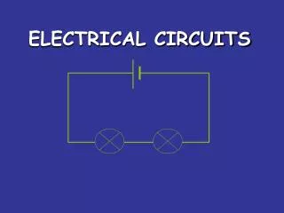
Electrical Circuit An electrical circuit is a circuitous path of wire and devices .
An example of a circuit with a DC. power supply in a series with a resistor, a parallel branch with a resistor and voltmeter, and an ammeter .
Basic Electric Circuit • The flashlight is an example of a basic electric circuit. • It contains a source of electrical energy (the dry cells in the flashlight), a load (the bulb) that changes the electrical energy into a more useful form of energy (light), and a switch to control the energy delivered to the load.
Laws of Electricity • Ohm’s law describes the relationship among potential, resistance and current in a resistive series circuit. • In a series circuit, all circuit elements are connected in sequence along a unique path, head to tail, as are the battery and three resistors. • Ohm’s Law may be written as: V = IR
Diagram for determining resistance and Voltage in a basic circuit
Kirchhoff’s Law • Kirchhoff’s current law states that the algebraic sum of currents around any point in a circuit is zero. • Kirchhoff’s voltage law states that the algebraic sum of the voltages around a closed electrical loop is zero.
Power Law • The power law states that the power in watts dissipated in a resistive element is given by the product of the current in amperes and the potential difference across the resistance in volts • P = IV
References • “Direct Current Circuits.” http://pneuma.phys.ualberta.ca/~gingrich/phys395/notes/node2.html • “Field effect transistors (FETs) as transducers in electrochemical sensors.” • http://www.ch.pw.edu.pl/~dybko/csrg/isfet/chemfet.html • Skoog, Holler, and Nieman. Principles of Instrumental Analysis. 5th ed. Orlando: Harcourt Brace & Co., 1998. • Shul’ga AA, Koudelka-Hep M, de Rooij NF, Netchiporouk LI. “Glucose sensitive enzyme field effect transistor using potassium ferricyanide as an oxidizing substrate.” Analytical Chemistry. 15 Jan. 1994.