Comprehensive Guide to Dimensioning and Creating 3D Models in Engineering Graphics
This guide covers essential practices in engineering graphics and parts mapping, focusing on accurate dimensioning and modeling techniques. It highlights the importance of establishing primary datum lines for accurate measurements and provides a systematic approach to dimensioning workpieces, including shafts and gears. The contents include utilizing available measuring tools, creating freehand sketches, and constructing detailed 3D models for components like worm gear shafts and bevel gear shafts. This resource is invaluable for engineering students and professionals aiming for precision in design and manufacturing.

Comprehensive Guide to Dimensioning and Creating 3D Models in Engineering Graphics
E N D
Presentation Transcript
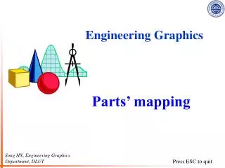
Engineering Graphics Parts’ mapping Song HX, Engineering Graphics Department, DLUT
All available measuring tools are in the desk drawers and one set is exhibited in the shelf
Dimensioning sample– shaft(18 basic dimensions) Determine the primary datum lines: Radial direction—the axis of the shaft Axial direction —the end plane of the biggest shoulder Dimensioning one by one (to avoid size chain closed). Looking up the appendices to give dimensions for the standard structures of manufacturing process, such as thread chamfer, escape of thread and grinding, the key seat. radial direction axial direction
Worm gear shaft Bevel gear shaft