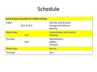
OS7200 Trainning Schedule
OS7200 Trainning Schedule. 1 Day 09:00 ~ 09:30 ; Introduction 09:30 ~ 12:30 ; System Oerview (Configuration, H/W description) : Mr. CJKIM 12:30 ~ 13:30 ; Lunch 13:30 ~ 17:00 ; Data module (- Network , Firewall Configuration/- DB Backup, Default DB

OS7200 Trainning Schedule
E N D
Presentation Transcript
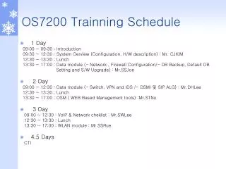
OS7200 Trainning Schedule • 1 Day 09:00 ~ 09:30 ; Introduction 09:30 ~ 12:30 ; System Oerview (Configuration, H/W description) : Mr. CJKIM 12:30 ~ 13:30 ; Lunch 13:30 ~ 17:00 ; Data module (- Network ,Firewall Configuration/- DB Backup, Default DB Setting and S/W Upgrade) : Mr.SSJoe • 2 Day 09:00 ~ 12:30 : Data module (- Switch, VPN and IDS /- DSMI 및 SIP ALG) : Mr.DHLee 12:30 ~ 13:30 ; Lunch 13:30 ~ 17:00 ; OSM ( WEB Based Management tools) :Mr.STNo • 3 Day 09:00 ~ 12:30 : VoIP & Network cheklist : Mr.SWLee 12:30 ~ 13:30 ; Lunch 13:30 ~ 17:00 ; WLAN module : Mr.SSRue • 4,5 Days CTI
OS7200 Training SAMSUNG Electronics September 2004
OS7200 Overview • Modular system comprising of up to 2 racks • Voice,Data & wireless convergence system • Fully expanded system supports up to a maximum of 160 ports except IP-Phone and WLAN Phone 120 ports • Each Rack can support up to a maximum of 80 station ports (Keyset/SLI) • Trunk ports capacity • Single rack with PRI = 122 ports - w/o PRI = 80 ports • 2 rack with PRI = 216 ports - w/o PRI = 160
OS7200 Overview • Range of new Features • Router • LAN Switch • Security : Firewall,VPN,Packet Filtering • Layer2 QoS : 802.1p/q • Layer3 QoS : CBQ, RTP Priority Queuing • Long Distance Ethernet : VDSLDSLAM • IP UMS(VM,AA,TTS,Voice recording,E-mail) • SIP Server • VoIP • WEB based Management • Multi WLI card support • Including 500Premium function
OS7200 Overview • OS7200 - Main Rack system • Floor, Wall or Rack Mountable • 5 universal card slots • RJ45 modulor Interface • dedicated MCP slot - slot 6 • Supports maximum of 80 station ports with 1 PSUs • Large LCD Phone support 24port with 1PSUs • 3 WLI card support
OS7200 Overview • OS7200 Expansion rack - 2 Racks • Floor, Wall or Rack Mountable • 10 universal card slots • Slot 1 in first cabinet used for LCP card • Second Rack is controlled by LCP card installed in dedicated MCP/LCP slot - slot 6 • Supports maximum of 160 station ports • E1/PRI card support in slot3 • Large LCD Phone support 48port
OS7200 Overview • Memory/Software • System Operating software is stored on a 16 Megabyte Smart Media Card • System boots from 512kbytes ROM and downloads to: • 32Mbytes of DRAM • Customer Database is stored in: • 4 Meg of SRAM
Smart Media • NAND Flash • Standard Data Structure • OS: DOS/FAT File system • Used to write data from Memory to Flash • 16MB SmartMedia(TM) is used for OS7200. • Dimension : 37.0(w) x 45.1(L) x 0.76(H) (mm) • Benefits • Easy Program Upgrade(No EPROMs required) • - Locally & Remotely • Easy Back Up of Customer DataBase • - Safe from the data loss in power failure • Programs installed on Smart Media include: • - MCP,LCP,TEPRI • Pre-Install Available in your office • - Useful for same category site installation
Microprocessors OS7200 Overview
OS7200 Overview • Programming • Self Configuring (w/o WIM) • MCP assigns Default Numbering Plan • 3 or 4 digits according to setting on MCP Card • Flexible numbering plan • Programming • via keyset • PC - using windows based DPAP-PCMMC • 4 levels - Technician, System Administrator, station user plus via PROG key • local and remote programming via LAN
OS7200 System Capacities Voice Switch . . Trunk/Station : Max. 216ch (PRI : 30ch) . Common Resource : MFS/R, R2CID, Miscellaneous LAN Switch . Max. 128port Slots . 32ch slot : 4 slot ( Main rack 3slot/Expansion rack 1slot) . 16ch slot : 6 slot . WIM card : Slot1 per each Rack . LIM card : slot2-5 per each Rack System IO Serial Communication Port ( Async.) ) . Main : 1 Ports ( MCP ) . Expansion : 1 Ports ( LCP ) LAN . Speed : 10/100 MBPS . Physical Connection : RJ-45 ( 1 Port ) . Built in LAN Board
OS7200 System Capacities Common Resources .Main .Shelf #1 : DTMF receiver 4Ch, DTMF sender 32Ch, Conference 5 party x 6 groups .Optional Daughter boards . MFM : DTMF receiver 12ch . RCM : R2 sender 30ch, R2 receiver 8ch. Caller ID receiver 14ch. . RCM2 : Caller ID Sender . MIS : External music 2port, Paging 1port, Loud bell 1port Common bell 1port, Dry contact 2port . Installed maximum - 1EA/MCP Miscellaneous Functions . Basic : Internal music 1 Port ( MCP ) . Expansion : MIS x 1 ( 1EA/MCP )
Operator Network Solution Feature Admin SME OS7200 System Highly Integrated “All-in-one” converged solution for total business communication VPN Tunnel xDSL, Metro Ethernet, VoIP, TDM, etc. Branch Office Home Working Fast Ethernet Fast Ethernet Mail Server Instant Messaging SIP Server VoIP-UMS Lite VoIP-UMS Pro Digital Phones VoWLAN Phone PC Console Smart Call Contact Center Video Conferencing WLAN AP IP Phones IP-VDSL WLAN IP Phone LDE Modem Web Browser System Master Phone Manager Fast Ethernet
OS7200 Rack • Common Rack for use as main rack or expansion rack • FAN reduce a heating problem • Slots 1-5 universal slots • Main rack Slots 3-5 assigned 32 time slots • Expansion rack Slots 3 assigned 32 time slots • Other slot assigned 16 time slots • Slot 0 dedicated for Processor cards (MCP or LCP) • AC power switches • DC (battery back up)
Slot 0 Front View of the Expansion Rack Slot 1 Slot 2 Slot 3 Slot 4 Slot 5 Slot 0 Slot 1 Slot 2 Front View of the Main Rack Slot 3 Slot 4 Slot 5 OS7200 Rack Configuration
1 PSUs can be installed in each rack PSU must be installed in backplane PSU provides the several voltage supply to the rack PSU supports 80 station ports or Station Equipment Power Units (SEPU) No redundancy Power to is controlled by Thermal sensor If the FAN module stoped, System halt after 24 hours. Power Supplies
Power Supplies PSU Comparison
48V power will be available 106 SEPUs Example Main rack with a PSU installed. The following interface cards are installed 16DLI (slot1), 16DLI card (slot2), 16DLI card (slot3), 4WLI card (slot4), TEPRI Card (slot5) Total power units of installed cards: 32+32+32+12+0 = 108. - Slot1 used Large LCD Phone 8 port and 2line LCD Phone 8 port. - Slot2 used Large LCD Phone 8 port and 2line LCD Phone 8 port. - Slot3 used Large LCD Phone 8 port and 2line LCD Phone 8 port. - Slot4 used WBS24 Combo 4 portsto power the keysets connected to 16DLI cards. If 16DLI over 8port Large LCD Phone, Power of 16DLI card stop. Power Supply Limitations
Installed in slot 0 of the main rack Has the following features: 256 time slot switch matrix Smart Media Card slot 3 Daughter board positions Memory Backup Switch 8 Position Dip Switch Reset button 4 Status LEDS Internal MOH source 1 SIO data rate adaptors 3 x RJ45 STP connected to LCP card Main Control Processor - MCP
MFM RCM MIS S2 S3 CHARGE Off Main Control Processor - MCP
Local Control Processor - LCP • Installed in Slot 0 of Expansion rack • Has the following features: • 2 status LEDs for LCP operation • 3 x RJ45 STP Connector for Connection to MCP and LCP card • Supplied with LINK cable
LINK1 LINK3 LINK2 Local Control Processor - LCP Connecting MCP Board to LCP Board Link Cable
Multi- Frequency Module - MFM • Installs in any daughter board position of the MCP cards. - maximum of 1 per processor card • Provides 12 DSPs for DTMF and Tone Detection SLT ports or DISA trunks
R2/CID Module - RCM • Installs into any of the MCP Cards • Consists of the following: • 14 CID receivers for CID trunks • 30 R2 MFC senders and 8 receivers • 8CID and 4R2 MFC
Miscellaneous Function Module - MIS • Installs in the following positions: • MCP - Main Rack systems only • 2 x RJ-45 sockets • Consists of the following: • 2 External Music sources • 1 External paging audio output • 1 loud bell relay audio output • 1 common bell relay contact closure • 2 software assigned relay contact closures
Dry contact #1 (For common bell) Dry contact #2 (For external page) Dry contact #3 (For external page) External Page Equipment Additional Page Equipment MISC 2 MISC 1 Miscellaneous Function Module - MIS Connecting External/Additional Page Equipment
MOH/BGM source of auser MOH/BGM source of auser MISC 2 MISC 1 Miscellaneous Function Module - MIS
8TRK card • Trunk - 8 loop start trunks • 8 Trunk Caller ID path support • Performs Polarity Reverse Detection(PRD) - option • Performs Metering Pulse Detection(MPD) - option
P1-P8 Port (RJ-45) (RJ-45) 8TRK card Connecting Common C.O. Lines
TEPRI Card • This card may be configured for PRI or E1 operation. • Supports Q-signalling in OS7200 system • Must be installed in slots 3-5 in main rack • maximum of 4 per system • Do not install this card with the power ON • Supports the following features • 8 Status LEDs • 1 x RJ-45 Sockets for PRI or E1 • 1 x RJ45 connector to allow upload of TEPRI software directly to the Card - generally not required • Reset Button - to reset the card • 8 position switch to set card operation
T1/E1/PRI Port (RJ-45) TEPRI Card
IP Telephony Module - MGI • Provides • 0 VoIP channels expandable to 16 using MGI2D daughter cards • Each MGI2D card support 4ch voice/fax • H.323/ SIP • G.711/G.723.1/G.729 voice compression protocols • Installed in any universal card slot with power OFF • Supports the following features • 8 Status LEDs • RJ-45 10/100 base-T LAN connection • 1 x RJ45 connector to allow upload of TEPRI software directly to the Card - generally not required • Reset Button - to reset the card
OFF : No memory backup ON : Available for memory backup (base default value) Option1 MGI2D Option2 MGI2D Option3 MGI2D Option4 MGI2D MGI Card