Download
1 / 19
190 likes | 300 Views
JWST FGS. “Phase C” Design of the JWST/FGS Tunable Filter Imager. Alex Fullerton STScI / UVic. TIPS/JIM June 15, 2006. Optical Design at PDR. Wavelength Coverage SW: 1.2 to 2.1 microns LW: 2.0 to 4.8 microns. SAT Recommendation. Wavelength Coverage SW: 1.2 to 2.1 microns

E N D
JWST FGS “Phase C” Design of the JWST/FGS Tunable Filter Imager Alex Fullerton STScI / UVic TIPS/JIM June 15, 2006
Optical Design at PDR Wavelength Coverage SW: 1.2 to 2.1 microns LW: 2.0 to 4.8 microns
SAT Recommendation Wavelength Coverage SW: 1.2 to 2.1 microns LW: 2.0 to 4.8 microns
SAT Recommendation Wavelength Coverage SW: 1.2 to 2.1 microns LW: 2.0 to 4.8 microns No cost savings to NASA.
SAT Recommendation Wavelength Coverage SW: 1.2 to 2.1 microns LW: 2.0 to 4.8 microns • No cost savings to NASA. • Removes: • 1 dichroic beamsplitter • 1 pupil/filter wheel assembly • 1 Fabry-Perot etalon • 1 camera TMA • 1 SCA • Half an optical bench • 80 kg
SAT Recommendation Wavelength Coverage SW: 1.2 to 2.1 microns LW: 2.0 to 4.8 microns Hard to achieve science goals with this wavelength coverage! • No cost savings to NASA. • Removes: • 1 dichroic beamsplitter • 1 pupil/filter wheel assembly • 1 Fabry-Perot etalon • 1 camera TMA • 1 SCA • Half an optical bench • 80 kg
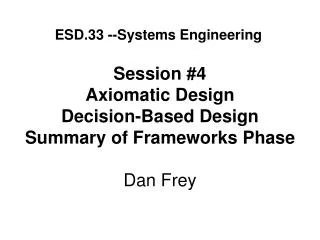
FGS-TFI Optical Layout at RDR / Phase C Pick-off Mirror Collimator TMA Fabry Perot Camera TMA Fold Detector Filters 100.00 MM
FGS-TFI Optical Layout at RDR / Phase C Pick-off Mirror Collimator TMA Fabry Perot Camera TMA Fold Detector Filters 100.00 MM
Fabry-Perot Etalons Optical path difference = 2µl cos Phase difference = (2/) 2µl cos + r m = 2µl cos + r /2 Tuning: For fixed m, on-axis (=0) l Detuning: For fixed m, l, off-axis () cos 1 2/2 µ=index of refraction
The SAT Challenge: Do More With Less • Improvements with respect to the PDR LW channel: • Significantly extended spectral waveband (1.5 to 5 μm) • Requirements: 1.6 to 4.9 μm [PDR LW: 2.0 to 4.8 μm] • Simplified – just 17 layers ! [PDR LW: 21 layers] • Minimal detuning of the etalon with angle-of-incidence An order of magnitude better than earlier versions of this coating! • Non-functional interval between 2.6 and 3 μm • Requirements: 2.5 to 3.2 μm • System operates at 2.4 μm, where NIRCam is non-functional
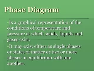
Reflectance and Phase 1.4 5.0 Non-Functional Waveband 1.2 4.5 1.0 4.0 0.8 3.5 Phase (radian) Reflectance 0.6 3.0 0.4 2.5 0.2 2.0 Reflectance Phase 0.0 1.5 1500 2000 2500 3000 3500 4000 4500 5000 Wavelength (nm)
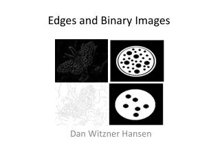
Etalon Gap and Spectral Resolution 160 10000 Non-Functional Waveband 140 9000 120 8000 100 7000 80 6000 Gap (nm) Resolution 60 5000 40 4000 20 3000 Resolution Gap 0 2000 1500 2000 2500 3000 3500 4000 4500 5000 Wavelength (nm)
Etalon Detuning - I max for TFI
Etalon Detuning - II max for TFI max for TFI
Pupil Wheel Filter Wheel Lyot Open Apo4 FFCal B6 Spare Apo3 Apo1 B5 B1 WCal Apo2 B4 B2 ND B3 Dual Wheel Configuration at PDR 8 position Filter Wheel allows for 6 blocking filters, an open for calibrations and one spare 8 position Pupil Wheel allows for a Lyot mask, up to 4 apodization masks, 2 calibration source positions and a neutral density position for target acquisition. Note: Calibration source positions on Pupil Wheel also serve as closed positions for dark calibrations
Current Dual Wheel Mechanism Motors Nine Position Wheels Resolvers Bracket
“Phase C” Dual Wheel Design • At least 9 positions are required to cover the full wavelength range (8 blocking filters + 1 “open” position) • Otherwise: there is a risk that the wavelength range will be restricted by the blocking filters (not the etalon!) • A larger wheel was not considered (mass). • Spare positions are available in the Pupil / Calibration Wheel Open
NIRCam bandpass TFI bandpass Key Performance Requirements * CSA-JWST-RD-0002 Rev B (JWST-RQMT-002069) • Wavelength Selection Flexibility • Good Sensitivity for Emission Line Objects • Emission Line Diagnostic Imaging • Coronagraphy for AGN studies & Extrasolar Planet Spectra
Etalon Stability / Repeatability • Stability depends on temperature control of etalon electronics • Etalon gap changes by 0.12 nm/K with prototype ECE • Issue: will flight electronics exhibit a temperature drift? • Assume: 1.2 nm/K (10 worse) • Implement: temperature control in ECE; stable to ~1 K • Expect: Over the course of a typical observation, etalon gap may vary by ~1.2 nm, or ~7% of a resolution element at 1.5 m. This is consistent with scientific requirements for photometric stability. • Can use onboard calibration lamp to check gap spacing during particularly long/critical observations. • Repeatability will depend upon the interval in question. • Over ~month, expected to be the same as the stability • Over longer intervals, will depend on aging of components • Mitigate by checking/updating TFI wavelength calibration


![[f´‚nE˘RIks]](https://cdn0.slideserve.com/1072532/f-ne-riks-dt.jpg)


![[f´‚nE˘RIks]](https://cdn2.slideserve.com/5310017/f-ne-riks-dt.jpg)