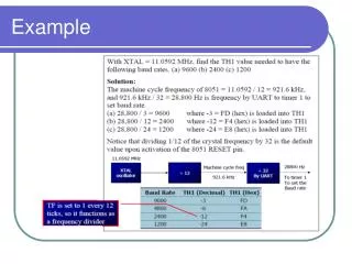
Example
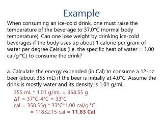
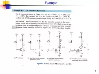
Example. Example contd…. Example. Thus the fixed bias circuit has the limitation that changes in does not change the base current. Thus the transistor can switch from active region operation to saturation or cut-off very easily. Analysis of four-resistor bias circuit.

Example
E N D
Presentation Transcript
Example Thus the fixed bias circuit has the limitation that changes in does not change the base current. Thus the transistor can switch from active region operation to saturation or cut-off very easily.
Analysis of four-resistor bias circuit • The voltage divider using R1 and R2 is useful in maintaining a constant bias to the base irrespective of changes in . This can be done by choosing the resistors so that the base current is a small fraction of the total current flowing through them • Also, since the base in not directly connected to the supply or ground an ac signal can be easily coupled through a coupling capacitor • Very small resistance can lead to overheating. Normally resistors are chosen so that 10-20 times base current flows through them. The Thevenin equivalent resistance RB is a parallel combination of R1 and R2 and given as The Thevenin voltage VB is given as
Small signal equivalent circuit: Signal notations The instantaneous values of current and voltage, iB(t) and vBE (t), respectively, are given as: Recall that for a diode the dynamic resistance rd is given as rd = nVT/IDQ. For BJT, the base-emitter behaves as the diode and the dynamic resistance is called rπ, where At room temperature: VT = 26 mV. Thus, for a typical β = 100, and typical IC = 1 mA, rπ = 2600 Ω
Small signal analysis Since ib (t) and Vbe (t) are ac quantities, they are related by the equation: From the relationship between collector and base current we also have: Using the relationships and The equivalent circuit can be drawn as in part (a) of the figure at the side Defining a quantity called transconductance gm as gm = β/rπ = ICQ/VT, we obtain The equivalent circuit can then be drawn as in part (b) of the figure at the side Example: A t room temperature a certain transistor has β = 150. Calculate gm and rπ if ICQ = 10 mA. We have gm = ICQ/VT = 10 mA/ 26 mV = 384.6 mS rπ = βVT/ICQ = 150x26 mV/10 mA = 390 Ω Solution: