Download
1 / 27
280 likes | 775 Views
Power Transmission Shaft. Irmydel Lugo Victor Molina Eladio Pereira. Purpose . To design a shaft that transmits 40 HP of power. It will be designed for infinite life. Also, it will be as light as possible (mass minimized). Applications. Electric motors Turbines Automotive transmission

E N D
Power Transmission Shaft Irmydel Lugo Victor Molina Eladio Pereira
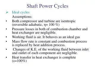
Purpose • To design a shaft that transmits 40 HP of power. • It will be designed for infinite life. • Also, it will be as light as possible (mass minimized)
Applications • Electric motors • Turbines • Automotive transmission • Manufacturing processes
Considerations • The torque acting on the shaft is fluctuating as the angular velocity changes. • The shaft will have cross sections of different diameters, which will make it more difficult to analyze dynamically.
Considerations • It was challenging to analyze all the four possible most critical sections and the effect of the fluctuating force on them. • The force is not changing sinusoidally, but it is decreasing exponentially as the angular velocity increases.
Why is this Shaft Different? • The design is relatively large, but it can be made smaller or bigger and it will work in the same way, as long as the proportions of diameters is kept. That makes it unique. • This shaft will resist for an infinite life and at the same time it will be economical.
Principal Challenge • Our biggest challenge with this project was finding the forces that were acting on the shaft, because they fluctuate with the revolutions applied (from 100 rpm to 3000 rpm)
Challenges • Another challenge was designing for a light material, but at the same time resistant to fatigue and deflection and to have infinite life. • Finding a material to cover our requirements, but being economical at the same time.
Design Details • These calculations were made with 3000 RPM
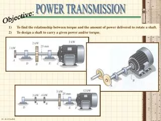
Design Details • For the next step, we made a diagram show how the forces are applied at the point of the spur gear, we assumed the angle of attack for the teeth of the spur gear is 20º
Stresses • Section with diameter of 2 in:
Stresses • Section with diameter of 4.8 in:
Stresses • Section with diameter of 6 in:
Material Selection: • To minimize the mass we have to minimize the relation . .
Material Selection: • Amongst the best materials to be used are aluminum alloys, titanium alloys and steel. • Also the ceramic and carbon fiber alloys, but due to the fact that the forces and stresses are so high, it is not recommendable to use them. • Aluminum 2024-T4 has the lowest ratio with 1.68 • Beta Titanium Alloy has a relation of 2.70 • 1020 Steel has a relation of 2.85.
Deflection • The maximum deflection occurs at where a and b are the distances between the applied force and the supports, where b > a.
Deflection • At this point the maximum deflection is obtained by the following equation; where P is 168.064lb, I is .78233 in^4 and L is 28 in.
Deflection • We obtained the value of E for Al-2024 T-4 (E = 10602 KSI), ASI-1020 (E = 29732 KSI) and Ti-15Mo5Zr3Al (β titanium alloy) (E = 10878 KSI).
Calculating Safety Factor • The safety factor was calculated by taking into consideration that we use infinite life as a goal of the design. • The highest safety factor was obtained by titanium, followed by steel and aluminum respectively.
Weakness of Our Shaft • There is no curvature between the sections of different diameters (no notch), so there are no stress concentrations to make the shaft more resistant to fatigue fracture.
Conclusions • We learned what materials we should have in mind when designing a shaft. • We also learned that the safety factor is different for each section of the component, so we should use the one of the most critical area. But we have to analyze all the possible critical sections, even if it is very exhausting.