Download
1 / 48
530 likes | 836 Views
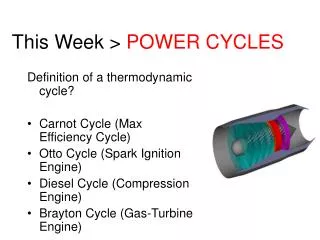
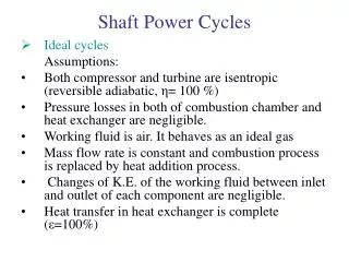
Shaft Power Cycles. Ideal cycles Assumptions: Both compressor and turbine are isentropic (reversible adiabatic, η = 100 %) Pressure losses in both of combustion chamber and heat exchanger are negligible. Working fluid is air. It behaves as an ideal gas

E N D
Shaft Power Cycles • Ideal cycles Assumptions: • Both compressor and turbine are isentropic (reversible adiabatic, η= 100 %) • Pressure losses in both of combustion chamber and heat exchanger are negligible. • Working fluid is air. It behaves as an ideal gas • Mass flow rate is constant and combustion process is replaced by heat addition process. • Changes of K.E. of the working fluid between inlet and outlet of each component are negligible. • Heat transfer in heat exchanger is complete (ε=100%)
Shaft Power Cycles • Description of simple cycle • Specific work, w • Thermal efficiency, η= w / q
Shaft Power Cycles • First law of thermodynamics (conservation of energy) • q – w = Δh • Compressor (adiabatic, q=0.) • Turbine
Shaft Power Cycles • Combustion chamber
Regeneration cycle (heat exchange cycle) To benefit from the exhaust, a regenerator is used to reduce the heat addition, the efficiency is improved since heat rejection is reduced.
Regeneration cycle (heat exchange cycle) Recall that .
Reheat Cycle In the reheat cycle, both of the heat addition and work done are increased. The thermal efficiency may increase or decrease depending on the values of T4 in comparison to T3.
Reheat Cycle For optimum conditions, i.e. maximum work, thus. This gives
Reheat Cycle Thus gives
Reheat Cycle The efficiency is calculated as
Cycle with reheat and heat exchange For ideal regenerator;
Methods for accounting for component losses • Performance of real cycles differ from ideal cycles for the following reasons: • Velocities in turbomachinery are high thus Δ K.E. is not equal to zero. • Compression and expansion are irreversible. • Friction losses in H.E. and CC. • H.E. effectiveness is less than 100% • Specific heat specific heat ratio are not constant through the cycle processes • More work is required for compression process to overcome bearings and friction in transmission between compressor and turbine • Cycle efficiency is different from unit efficiency • Some compressed air is bled for turbine blade cooling.
Stagnation properties The energy equation for a flow coming to rest is Whereh is the static enthalpyO refers to the stagnation conditionC is the velocity
Stagnation properties • Thus:
Stagnation properties • Thus the first law equation is
Compressor and turbine efficiency Compressor efficiency
Compressor and turbine efficiency Turbine efficiency
Polytropic efficiency Consider a compressor of different stages. The Polytropic efficiency (defined as the isentropic efficiency of an elemental stage in the process such that it is constant throughout the whole process) given by
Polytropic efficiency • For an expansion (such as a turbine)
Polytropic efficiency • For a compressor • For a turbine
Mechanical Losses and Variations in specific heats Mechanical Losses Variations in specific heats
Example 2.1 • A heat exchange cycle having the following data: • turbine inlet temperature 1100(K) • compressor pressure ratio 4.0 • isentropic efficiency of compressor 0.85 • isentropic efficiency of turbine 0.87 • combustion efficiency 0.98 • mechanical transmission efficiency 0.99 • heat exchange effectiveness 0.80 • ambient conditions 1(bar), 288 (k) • pressure losses • combustion chamber 2% of compressor delivery pressure • heat exchanger air side 3% of compressor delivery pressure • heat exchanger gas side 0.04 (bar)
Example 2.2 • A simple gas turbine with free turbine power having the following data: • turbine inlet temperature 1350(K) • compressor pressure ratio 12.0 • isentropic efficiency of compressor 0.86 • isentropic efficiency of each turbine 0.89 • combustion efficiency 0.99 • mechanical efficiency of each shaft 0.99 • ambient conditions 1(bar), 288 (k) • combustion chamber pressure loss 6% comp. deliv. pres. • exhaust pressure loss 0.03(bar)
Example 2.3 • Reheat Cycle • net work output 240 MW • turbine inlet temperature 1525(K) • compressor pressure ratio 30 • polytropic efficiency for compressor and turbines • 0.89 • Pressure loss in first combustor is 2% • Pressure loss in second combustor 4% • exhaust pressure 1.02 (bar) • ambient conditions 288(K), 1.01(bar) Assume that pressure ratios in HP and LP turbines are equal