Download
1 / 9
90 likes | 140 Views
Explore the distributed switch architecture of VoIP networks, from call agents to connections, bandwidth usage, and call flow paths.

E N D
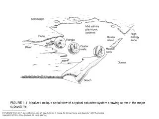
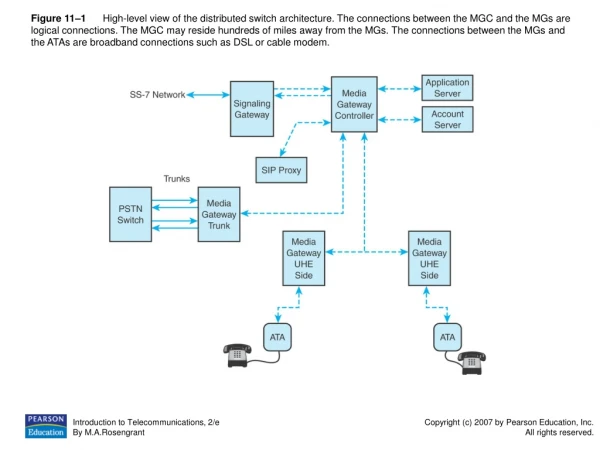
Figure 11–1 High-level view of the distributed switch architecture. The connections between the MGC and the MGs are logical connections. The MGC may reside hundreds of miles away from the MGs. The connections between the MGs and the ATAs are broadband connections such as DSL or cable modem.
Figure 11–2 A call agent, also called a soft switch or an MGC, may be combined with the residential MG and the trunk MG to provide VoIP service on a small scale, such as for a corporate internal VoIP network.
Figure 11–3 A call flowing from Los Angeles to New York City is set up by the MGC. The call path flows from the MG in Los Angeles to the MG in New York.
Figure 11–4 A broadband device such as a cable modem or DSL modem interconnect to the ATA via an Ethernet connection. The ATA connects to the standard analog telephone set via an RJ-11 analog telephone port.
Figure 11–5 Simple SIP ladder showing how a call is established and disconnected.
Figure 11–6 RTP header contains field used to assist UDP in transmitting real-time traffic such as VoIP.
Figure 11–7 RTP flow requires 80 kbps of bandwidth in one direction: 80 kbps path from sender to receiver and 80 kbps path from receiver to sender. One call between two people eats up 160 kbps of bandwidth across the network.
Figure 11–8 A call traveling between Joe and Carol traverses the IP network as RTP flows and the PSTN as traditional DS-0 64 kbps voice traffic. Shaded boxes exist in the PSTN. Nonshaded boxes make up the VoIP network.
Figure 11–9 A call made between customers on the same network travels between MGs to the end devices.