Download

1 / 24
240 likes | 375 Views
Performance Bounds for Hybrid Flow Lines: Fundamental Behavior, Practical Features and Application to Linear Cluster Tools. Kyungsu Park and James R. Morrison Industrial and Systems Engineering IEEE CASE 2012 – August 20 – 24, 2012 – Seoul, South Korea. Presentation Overview. Motivation

E N D
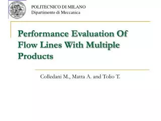
Performance Bounds for Hybrid Flow Lines:Fundamental Behavior, Practical Features and Application to Linear Cluster Tools Kyungsu Park and James R. Morrison Industrial and Systems Engineering IEEE CASE 2012 – August 20 – 24, 2012 – Seoul, South Korea
Presentation Overview • Motivation • System Description: Hybrid Flow Lines • Upper Bound on Completion Times • Application to Linear Cluster Tools • Concluding Remarks
Motivation: Flow Line Application • It is common to abstract intractable problem to simple one • Flow line can be used as model for manufacturing systems • Application • Automobile assembly plants[A. Agnetis et. al. 1997] • Printed wiring board assembly[T. Sawik 2002] • Printed circuit board (PCB) manufacturing[S. Piramuthu et. al. 1994, R. Wittrock 1985, 1988] • Design of a printer production line in Hewlett-Packard[M. Burman et. al. 1998] • Using [Gershwin 1987] and [Dallery, David, and Xie 1988] • $280 million in printer shipments and additional revenues • Determine how much buffer space is needed with approximate decomposition method • Semiconductor equipment modeling and control[S. Abspoel et. al. 2000]
Motivation: Semiconductor Wafer Manufacturing • Global revenue in 2010: US $ 304 Billion+[1] • High construction cost for fabricator: US $ 5 Billion+[2] • Cluster tools • Capital equipment in semiconductor manufacturing • Clustered photolithography tools: US $ 20 Million+ • Typically the bottleneck of the fabricator • Key yield and cycle time contributor • Accurate, expressive, practical and computationally tractable equipment models for fab-level simulation should be developed [5] [3] [4] [1] HIS iSuppli April 2011 [2] ElpidaMemory, Inc., available at http://www.eplida.com [3] http://www.rocelec.com/manufacturing/wafer_fabrication/ [4] http://www.portlandtribune.com/news/print_story.php?story_id=123429419318201800 [5] “Immersion Lithography: Photomask and Wafer-Level Materials,”Roger H. French and Hoang V. Tran. Annual Review of Materials Research, Vol. 39, 93-126.
Motivation: Flow Line Theory • No results for completion times with multiple classes of customers and multi servers
System Description: Hybrid Flow Lines • One module can hold at most one wafer • Wafer advance: Service complete & module for next process available • Buffers can be modeled as a process module with zero process time • Multi class of customer • No overtaking (One process can hold only one class) Question: • Can we develop an intuitive description of exit times? • Can we reduce the computation?
System Description: Hybrid Flow Lines • EEEs (Elementary Evolution Equations) • Xw,m: entry time of wafer w to process m • c(w): class of wafer w • tc(w)m: service time of wafer w for process Pm • R(m): number of parallel modules for process m
System Description: Hybrid Flow Lines • Single customer class: • Multi customer class: • R’(m) = R(m) if class does not change • R’(m) = 1 if class changes Xw,m = max { Xw,m-1 + τc(w)m-1 , Xw-R(m),m+1} Wafer is ready to enter Process is available Xw,m = max { Xw,m-1 + τc(w)m-1 , Xw-R’(m),m+1, Xw-1,m} Preventing overtaking
Upper Bound on Completion Times • E(w): the completion time of wafer w from the system • aw: arrival time of wafer w • Proof: using Max-plus algebra • Theorem 1: Upper Bound on Completion Times For a hybrid multiclass flow line without overtaking, with the initial conditions E(w) = -∞ for w ≤ 0.
Upper Bound on Completion Times • Example • Constant process time regardless of class • Upper Bound on Completion Times • If c(w)≠c(w-1), thus class changes, • If not, t2 t1
Upper Bound on Completion Times • Example: c(w)=c(w-1) t2 t1 No contention inside the system
Upper Bound on Completion Times • Example: c(w)=c(w-1) t2 t1 Last contention of wafer w at process 1 with wafer (w-2)
Upper Bound on Completion Times • Example: c(w)=c(w-1) t2 t1 Last contention of wafer w at process 2 with wafer (w-3)
Upper Bound on Completion Times • Example: c(w)=c(w-1) t2 t1 Preventing overtaking
Upper Bound on Completion Times • Example: c(w)=c(w-1) t2=60sec t1=20sec Wafer5 Wafer4 Wafer1 Wafer2 Wafer3 ? ? ? ? Arrive120sec
Upper Bound on Completion Times • Add new variable P(w,k) to describe setup conditions(e.g. process setups, module setups and state-dependent setups) • Proposition 1: Inequality of Theorem 1 • Theorem 2: Upper Bound on Completion Times For a hybrid multiclass flow line with setups, with the initial conditions E(w)=-∞ for w≤0. The bound of Theorem 1 cannot be improved to strict equality. • Please refer to the paper for other lemmas and corollaries
Application to Linear Cluster Tools • Accurate, expressive, practical and computationally tractable equipment models for fab-level simulation should be developed • Circular Cluster Tools • Much effort has beendevoted • Here, we develop a model for linear cluster tools
Application to Linear Cluster Tools • Linear Cluster Tools • Connected in a linear flow • Consist of a collection of paired process chambers (“links”) • Each link has its own wafer transport robot FOUP FOUP arrives exits 1a. CVD 300s 1c. CVD 300s 2a. PVD 120s 5. PVD 60s 3. PVD 60s 2b. CVD 120s 1d. CVD 300s 1b. CVD 300s 4. PVD 60s 6. PVD 60s 2009, Radloff et. al. 2007, Yi et. al. 2007, Meulen Rolling setups to reduce first wafer delay are introduced. New flexible tool configuration is proposed by BlueShift Tech. Robotic scheduling for steady state is studied.
Application to Linear Cluster Tools Linear Cluster Tool Abstract Flow Line Model Incorporate rolling setups Upper bound on completion times for rolling setups Include “Robotic Overhead” (based on scheduling from [2007, Yi et. al.]) Approximation: Exit times from a linear cluster tool (APPX)
Application to Linear Cluster Tools: Simulation Results • Compare with detailed simulation • Detailed simulation can be treated as upper bound of optimality • 4 different wafers/lot (W = 3, 5, 10, 24) • Average train size is 3 (T = 3) • Setup duration: Uniform [100,300] • 18,000 lots x 20 replications • Throughput: number of complete wafers per hour
Concluding Remarks • Develop a model for hybrid flow lines with multiple customer classes and no overtaking • Obtain an upper bound on departure times • Extend these ideas and results for a general class of setups • With an application to linear cluster tools • Obtain bounds on hybrid flow lines with rolling setups and develop approximations for linear cluster tools • JIT throughput estimation with about 5% error and 100 times less computation than detailed simulation • Future direction • Compare the performance with circular cluster tools • Identify classes of systems for which the bounds achieve equality • Obtain a lower bound on departure times
Flow Line Models • Accuracy of Flow Line Models • Control of cluster tool robot: • Robot essential: Petri net, MIP models, etc. • Throughput of clustered photolithography tools? • Robot overhead can be incorporated into process times • Bottleneck behavior dictates throughput Cluster Tools ? = Flow Line Models
Flow Line Models • Throughput of cluster tools: • Good robot policy provides bottleneck throughput • Typical robot overhead is small and easy to include • Practical study: 0.5% throughput error and 3% cycle time error (Morrison 2011) • Cycle time estimation for cluster tools (Park and Morrison 2011) < Cycle time estimation error>