NETWORK OPERATING DIVISION Operating Effectiveness
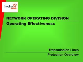
NETWORK OPERATING DIVISION Operating Effectiveness. Transmission Lines Protection Overview. Operating Effectiveness Training & Development. Transmission Lines LH1 Protection Overview. Hydro One Networks Inc 49 Sarjeant Drive Barrie, Ontario Canada, L4N 4V9 Phone (705) 719-3528.

NETWORK OPERATING DIVISION Operating Effectiveness
E N D
Presentation Transcript
NETWORK OPERATING DIVISIONOperating Effectiveness Transmission Lines Protection Overview
Operating Effectiveness Training & Development Transmission Lines LH1 Protection Overview Hydro One Networks Inc 49 Sarjeant Drive Barrie, Ontario Canada, L4N 4V9 Phone (705) 719-3528 Revised: November 4, 2008 The information in this document is for reference and is to be used as a guide only. The OE Training Section makes no representation or warranty, expressed or implied, that the information contained within is current. The information included is subject to change. It is solely your responsibility to ensure that you are using up-to-date documents, prints and information. Please notify the HONOC Operating Effectiveness Training Section of required updates and/or modifications.
Objectives Transmission Lines Protection Through the use of this presentation participants will learn and understand Transmission Lines Protection. Emphasis is on: • Functionality • Limitations • Instructions and Procedures • Support Services. Cont…
Transmission Lines Protection Overview. This presentation will cover: What transmission line protection is, Why the need for line protection Principles of Operation ( Impedance), Different Operational zones Various types or schemes Exceptions and Anomalies Transfer Trip Channels Permissive Echo
Transmission Lines Protection Overview. This presentation will cover: LH1 configuration Micro-wave communications Power Line Carrier communications Fibre-Optic Digital communications Various types or schemes
Station ‘A’ Station ‘B’ Power flow Transmission Lines Protection Overview. We first must understand what a transmission line is. A transmission line is a high voltage circuit designed to carry a high amount of power over great distances between points. In some cases, this could be simply between two points as shown.
Transmission Lines Protection Overview. • In more complicated configurations there could be: • Multiple terminal stations • Multiple tap stations • Combinations of both Station ‘D’ Station ‘A’ Station ‘B’ Power flow Station ‘E’ Station ‘F’ Station ‘C’
Transmission Lines Protection Overview. To begin, we will look at a simple two ended circuit Station 'Z' Station 'Y' Station 'Y' is a terminal that has two breakers on the circuit. Station 'Z' is also a two breaker terminal for the circuit.
Transmission Lines Protection Overview. Simple two ended circuit Station 'Z' Station 'Y' The circuit that travels between Station 'Y' and Station 'Z' is a high voltage open air transmission line and as such is vulnerable to external influences.
Transmission Lines Protection Overview. Simple two ended circuit Station 'Z' Station 'Y' A fault could develop anywhere along the circuit causing fault current to flow between phases and/or to the ground.
Transmission Lines Protection Overview. Simple two ended circuit Station 'Z' Station 'Y' If there is no way of removing this faulted equipment from service, it will remain faulted eventually causing danger to the public, damage to equipment or even lead to a system wide disturbance.
Transmission Lines Protection Overview. Simple two ended circuit How does the protection system see the fault? Station 'Z' Station 'Y' Protection systems will sense the fault and clear the circuit removing it from service.
Transmission Lines Protection Overview. Simple two ended circuit There are many ways in which faults can be detected. For transmission circuits the most common method is by using impedance .
Transmission Lines Protection Overview. Simple two ended circuit Current (CT) Voltage (CVT) Station 'Z' Station 'Y' At each end of the line there are both voltage sensing devices and current sensing devices
Transmission Lines Protection Overview. Simple two ended circuit These sensing devices monitor line voltage and line current on a continuous basis. Under normal circumstances, the current will be at expected normal values and the voltage will be at the system normal.
Transmission Lines Protection Overview. Simple two ended circuit The Impedance is derived by placing the voltage and current into a ratio using OHMS law. Voltage 230,000 = 115 ohms Impedance = Current 2,000 Voltage = 230,000 volts Current = 2,000 amps
Transmission Lines Protection Overview. Simple two ended circuit If a fault occurs then these quantities will be disrupted causing the ratio to greatly change. 150000 230,000 = 115 ohms = 3 ohms Impedance = 50000 2,000 Voltage = 230,000 volts Voltage = 150,000 volts Current = 2,000 amps Current = 50,000 amps
Trip Setting range Normal Operating range 115 ohms 3 ohms Transmission Lines Protection Overview. Simple two ended circuit The impedance is set to a certain range. Anything outside of that set range is considered a fault and will trip the circuit. Impedance is outside of preset range – Circuit will trip. 50000 Amps 2000 Amps 150000 Volts 230000 Volts
Transmission Lines Protection Overview. Simple two ended circuit Station 'Z' Station 'Y' The idea is to set the impedance such that for any fault on the line, the protections will see the changes in voltage, current and the ratio between them, covering 100% of the circuit.
Transmission Lines Protection Overview. Simple two ended circuit Station 'Z' Station 'Y' With this type of impedance detection, it would be very difficult to set the range to exactly cover 100% of the circuit due to tolerances in measuring equipment.
Transmission Lines Protection Overview. Simple two ended circuit Station 'Z' Station 'Y' The settings could be set: Too short. Under protected Too long. Over protected
Transmission Lines Protection Overview. Simple two ended circuit Station 'Z' Station 'Y' To correct this problem, specific zones of protection have been created.
Transmission Lines Protection Overview. Simple two ended circuit Station 'Z' Station 'Y' Zone 1 – 80-85% Zone 2 – 125-150% Zone 1 – Is set to cover 80-85% of the circuit and is instant. Zone 2 – Is set to cover 125-150% of the circuit but is generally a timed protection.
Transmission Lines Protection Overview. Zone 1 Protection Station 'Z' Station 'Y' Zone 1 – 80-85% Zone 1 – Is set to cover 80-85% of the circuit and is instant. Zone 1 protection is generally known as Direct Underreach
This area overlaps and is Instantaneous protection from both Station 'Y' and Station 'Z'. This area Instantaneous protection from Station 'Z' only. This area Instantaneous protection from Station 'Y' only. Transmission Lines Protection Overview. Zone 1 Protection There is a limit to the protection when using Direct Underreach Station 'Z' Station 'Y'
If a fault occurs here, ‘Y’ Zone 1 will see it and send a trip signal called… Transmission Lines Protection Overview. Zone 1 Protection To overcome this limit communication is used between ends. Station 'Z' Station 'Y' Transfer Trip
1 T/T Rx 2 Transfer Trip Transmission Lines Protection Overview. Transfer Trip Communication is accomplished by a variety of media but will not be discussed right now. Station 'Z' Station 'Y' At Station 'Y' both Zone 1 and Zone 2 will see the fault. Station 'Y' Zone 1 will trip instantly and send Transfer Trip Station ‘Z' will receive Transfer Trip and trip its terminal breakers instantly.
How do we protect this area from Station 'Y'? How do we protect this area from Station 'Z'? Transmission Lines Protection Overview. Simple two ended circuit The answer is to use another zone designed to reach all the way across the circuit. There is another limit to the protection when using Direct Underreach Station 'Z' Station 'Y'
Transmission Lines Protection Overview. Simple two ended circuit Zone 2 Station 'Z' Station 'Y' Zone 2 is set to ‘see’ 125-150% of the circuit. The protection will overlook into adjacent zones and could cause erroneous trips for faults outside of the zone. To prevent this Zone 2 protection is generally made to be timed.
Transmission Lines Protection Overview. We will look at Zone 2 independent of Zone 1 Zone 2 Station 'Z' Station 'Y' Zone 2 is set to ‘see’ 125-150% of the circuit. Although Zone 2 is normally timed, there is a need for the Zone 2 protection to be instantaneous in order to satisfy rapid removal of the transmission circuit in a faulted condition.
Transmission Lines Protection Overview. Zone 2 Protection Station 'Z' Station 'Y' The rapid removal will be by using Zone 2 in a: Permissive Overreach scheme or Directional Comparison scheme
2 Transmission Lines Protection Overview. Permissive Overreach Station 'Z' Station 'Y' Zone 1 Limit In Permissive Overreach each Station has a timed Zone 2. If a fault occurs outside of Station 'Z' Zone 1 as shown above, only the Station 'Z' Zone 2 will see it. When the Zone 2 ‘sees’ the fault it starts a timer (400ms).
1 2 2 Permissive Signal Transmission Lines Protection Overview. Permissive Overreach Station 'Z' Station 'Y' Zone 1 Limit At Station 'Y' both Zone 1 and Zone 2 will see the fault. Station 'Y' Zone 1 will trip instantly Station 'Y' Zone 2 will see the fault and will send Permission to Station 'Z' Zone 2 to trip instantly instead of timed.
2 Transmission Lines Protection Overview. Directional Comparison Station ‘Z’ Station ‘Y’ Zone 1 Limit In Directional Comparison each Station has Instant Zone 2 coverage. If a fault occurs outside of Station ‘Z’ Zone 1 as shown above, only the Station ‘Z’ Zone 2 will see it. When the Zone 2 ‘sees’ the fault it will trip instantly.
2 Transmission Lines Protection Overview. Directional Comparison Station ‘Z’ Station ‘Y’ Zone 1 Limit This Instantaneous tripping, however, could pose a problem if the fault is outside of the protected circuit, but still inside the Zone 2 reach. The fault will be seen by the Zone 2 protection and will cause the circuit to erroneously trip for this out of zone fault.
2 Transmission Lines Protection Overview. Directional Comparison Station ‘Z’ Station ‘Y’ Zone 1 Limit For example: The fault is located on the adjacent circuit. Station ‘Z’ Zone 2 ‘sees’ the fault and will trip instantly Only the circuits breakers of the faulted circuit should trip
OM3 2 Block Signal Transmission Lines Protection Overview. Directional Comparison The OM3 will sense the fault as well and send a block signal to the opposite Zone 2 preventing it from tripping instantly. Station ‘Z’ Station ‘Y’ X To correct this a 3rd Zone is employed This is the Directional Comparison element which employs a relay known as an OM3 relay and is set to look backwards If a fault occurs out of zone it trips its local breakers. The Zone 2 at Station ‘Z’ will also see the fault and try to trip its breakers instantly.
OM3 OM3 Transfer Trip Block Signal Permissive Signal 1 1 2 2 Permissive Signal Transfer Trip Block Signal Transmission Lines Protection Overview. Protection review Station 'Z' Station 'Y' Station ‘Z’ Zone 3 OM3 Station ‘Z’ Zone 2 Station ‘Z’ Zone 1 Station ‘Y’ Zone 1 Station ‘Y’ Zone 2 Station ‘Y’ Zone 3 OM3 The protections will all have a Zone 1 Direct Under reach and Zone 2 will have either Permissive Overreach or Directional Comparison but not both. Directional Comparison is Instant unless it receives a Block Signal from the opposite end Zone 3 OM3 element where it will then trip timed. In some cases Zone 2 may be different in each Group, Group A Zone 2 could have Permissive Overreach where Group B could have Directional Comparison These protections are referred to as Groups. Each terminal will have duplication of each group and will be known as Group A and Group B. Permissive Overreach is Timed unless it receives a Permissive Signal from the opposite end Zone 2 protection where it will then trip instantly. Zone 2 can be Permissive Overreach or Directional Comparison Each Station Zone 1 will send Transfer Trip to opposite end station tripping its breakers. Each Station has a Zone 1 Direct Underreach covering 80-85% of the circuit. Each Group A and Group B are generally clones of each other witha Zone 1 Direct Underreach and a similar Zone 2. Each Station has Zone 2 covering 125-150% of the circuit.
OM3 OM3 Permissive Signal Block Signal Transfer Trip 1 2 1 2 Permissive Signal Block Signal Transfer Trip Transmission Lines Protection Overview. Protection review Station 'Z' Station 'Y' Station ‘Z’ Zone 3 OM3 Station ‘Z’ Zone 2 Station ‘Z’ Zone 1 Station ‘Y’ Zone 1 Station ‘Y’ Zone 2 Station ‘Y’ Zone 3 OM3 This is what represents a basic line protection. Two Zones with a dual redundancy built in.
OM3 OM3 Permissive Signal Transfer Trip Block Signal 1 2 1 2 Permissive Signal Transfer Trip Block Signal Transmission Lines Protection Overview. Lets look at when a terminal is Out of Service with its line disconnect open Station 'Z' Station 'Y' Station ‘Z’ Zone 3 OM3 Station ‘Z’ Zone 2 Station ‘Z’ Zone 1 Station ‘Y’ Zone 1 Station ‘Y’ Zone 2 Station ‘Y’ Zone 3 OM3 The line switch at Station ‘Y’ is OPEN As a result, Station ‘Y’ Protections no longer see the circuit.
Transfer Trip 2 1 Transmission Lines Protection Overview. Lets look at when a terminal is Out of Service Station 'Z' Station 'Y' Station ‘Z’ Zone 2 Station ‘Z’ Zone 1 Transfer Trip is Blocked to opposite terminal breakers If a fault occurs within the Zone 1, both Zone 1 and Zone 2 protections will see the fault and the Zone 1 will high speed trip the terminal at Station ‘Z’.
Permissive Signal 2 1 Permissive Echo Signal Transmission Lines Protection Overview. Lets look at when a terminal is Out of Service ‘B’ Pallets Station 'Z' Station 'Y' Station ‘Z’ Zone 2 Station ‘Z’ Zone 1 If a fault occurs outside of Zone 1, only Zone 2 protections will see the fault and will timed trip the terminal at Station ‘Z’. To correct this, the Permissive Signal is returned or Echoed back to the sending terminal and it will then trip instantly. This signal is keyed on at all times.
1 2 1 2 Transmission Lines Protection Overview. Communication Powerline Carrier- Wave Trap Station 'Y' Station 'Z' Fibre-Optic Digital Tele-protection MicroWave In order for the Protection signals to travel from one station to another, a communications medium is required. There are several types used today.
Transmission Lines Protection Overview. Micro-Wave Communication Station 'Y' Station 'Z' Microwave signals are transmitted between points. These are known as Guard Tones The Guard Tones typically consist of 4 Transfer Trip Tones and 2 Permissive / Blocking Tones We will call them… A large microwave transmission tower is built at each end of the circuit
Transmission Lines Protection Overview. Micro-Wave Communication Station 'Y' Station 'Z' Transfer Trip Channel #1 Transfer Trip Channel #2 Transfer Trip Channel #3 Transfer Trip Channel #4 Permissive / Block Channel #1 Permissive / Block Channel #2
Transmission Lines Protection Overview. Micro-Wave Communication Station 'Y' The question arises. Why so many Tones? Station 'Z' Here’s why…. Microwave is: - influenced by external forces - a line of sight communication
Transmission Lines Protection Overview. Micro-Wave Communication Station 'Y' Station 'Z' Microwave is a radio signal and uses air to travel through. When the air changes properties, it distorts the path of the microwave. This is known as- MicrowaveFading
Transmission Lines Protection Overview. Micro-Wave Communication Station 'Y' Station 'Z' • Distortions in the air can be caused by changes in: • Temperature • Pressure • Humidity • Precipitation • Fog • and many other atmospheric factors.
Transmission Lines Protection Overview. Micro-Wave Communication Station 'Z' Microwave is also a “Line of Sight” communications Station 'Y' Trees Buildings Any type of physical obstruction will affect the path of the signal
Transmission Lines Protection Overview. Micro-Wave Communication Station 'Z' Station 'Y' To correct for these limits. Pathways are carefully determined to minimize external influences.