Download
1 / 32
320 likes | 463 Views
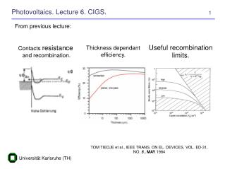
International School on Concentrated Photovoltaics, Ferrara 2-6 September 2006 “CHARACTERIZATION OF CONCENTRATED LIGHT BEAMS WITH APPLICATIONS TO SOLAR CONCENTRATORS ” Part B: “Radiometric methods” Antonio Parretta ENEA – Bologna. OUTLINE. 1. The Double Cavity Radiometer: i) Theory

E N D
International School on Concentrated Photovoltaics, Ferrara 2-6 September 2006 “CHARACTERIZATION OF CONCENTRATED LIGHT BEAMS WITH APPLICATIONS TO SOLAR CONCENTRATORS” Part B: “Radiometric methods” Antonio Parretta ENEA – Bologna
OUTLINE 1. The Double Cavity Radiometer: i) Theory ii) Practical realization iii) Calibration iv) Applications 2. Introduction to radiometers for solar concentrators with cylindrical receivers Ist International School on Concentrated Photovoltaics, Ferrara 2-6 September 2006
DOUBLE-CAVITY RADIOMETER (DCR)(1) The optical model (1)Patented Ist International School on Concentrated Photovoltaics, Ferrara 2-6 September 2006
to voltmeter or lock-in P0 photodetector m sphere 1 in sphere 2 Pm Pin c Pc(r) i j Pi G2 G1 Pc(l) Pj Radiometer with two coupled integrating spheres Ist International School on Concentrated Photovoltaics, Ferrara 2-6 September 2006
The optical model Energy conservation law applied to sphere 1: Energy conservation law applied to sphere 2: Ist International School on Concentrated Photovoltaics, Ferrara 2-6 September 2006
The optical model Irradiance into sphere 1: Irradiance into sphere 2: Ist International School on Concentrated Photovoltaics, Ferrara 2-6 September 2006
The optical model Power at input “in”: Irradiance incident on the photodetector “m”: Radiant power on the photodetector “m”: Ist International School on Concentrated Photovoltaics, Ferrara 2-6 September 2006
The optical model We define the following Attenuation Factors: i) ii) Ist International School on Concentrated Photovoltaics, Ferrara 2-6 September 2006
The optical model Attenuation factor for the irradiance (flux density measurements) iii) Attenuation factor for the power (power measurements) iv) Ist International School on Concentrated Photovoltaics, Ferrara 2-6 September 2006
The optical model Attenuation Factors: i) ii) iii) iv) Ist International School on Concentrated Photovoltaics, Ferrara 2-6 September 2006
sp cl of win wof is1 is2 wc wm m pr rad1 Modelling of a prototype of DCR We model the radiometer for measurements of the total power incident on the concentration cell SunPower HECO252, used as photovoltaic receiver in the concentrating system PhoCUS operating at ENEA Research Centre of Portici.
C-Module of the PhoCUS Project C-Module Assembled SunPower HECO252 cell Ist International School on Concentrated Photovoltaics, Ferrara 2-6 September 2006
Glass window SP-HECO252 cell SS frame Optical fibre DCR window SP-HECO252 cell Modelling of SP cell and optical fibre Ist International School on Concentrated Photovoltaics, Ferrara 2-6 September 2006
P0 Sm Sin Pm Pin Pc(r) Sc G2 G1 Pc(l) Pof Sof The optical model (prototype) Sphere diameter, d = 5 cm; input window area, Sin = 1.1 × 1.1 = 1.21 cm2; photodetector window area, Sm = 1.5 × 1.5 = 2.25 cm2; optical fiber head area, Sof = 0.196 cm2. Variable quantities: aperture area, Sc = 0.1÷2.0 cm2; wall reflectance, Rw = 92÷99%. Ist International School on Concentrated Photovoltaics, Ferrara 2-6 September 2006
The optical model (prototype) Ist International School on Concentrated Photovoltaics, Ferrara 2-6 September 2006
Attenuation factor for power Attenuation factor of the DCR radiometer, calculated as function of the intermediate aperture area, Sc, for some values of the wall reflectance, Rw.
DOUBLE-CAVITY RADIOMETER (DCR) Ray tracing Ist International School on Concentrated Photovoltaics, Ferrara 2-6 September 2006
Ray tracing (prototype) Ray tracing by TracePro Ist International School on Concentrated Photovoltaics, Ferrara 2-6 September 2006
DOUBLE-CAVITY RADIOMETER (DCR) The thermal model Ist International School on Concentrated Photovoltaics, Ferrara 2-6 September 2006
Thermal model Heat generated on the SunPower cell: where: Ist International School on Concentrated Photovoltaics, Ferrara 2-6 September 2006
Efficiency of SP-HECO252 cell Efficiency versus concentration Ist International School on Concentrated Photovoltaics, Ferrara 2-6 September 2006
Efficiency of SP-HECO252 cell Efficiency of SP-HECO252 cell versus concentrationat at input of DCR Ist International School on Concentrated Photovoltaics, Ferrara 2-6 September 2006
Generated Heat Heat generated on the SP-HECO252 cell of DCR vs. light concentration (medium) at input, for different Sco values. Ist International School on Concentrated Photovoltaics, Ferrara 2-6 September 2006
Generated Heat Heat generated on the SP-HECO252 cell of DCR vs. light concentration (high) at input, for different Sco values. The curves are truncated at Gm = 200 suns. Ist International School on Concentrated Photovoltaics, Ferrara 2-6 September 2006
DOUBLE-CAVITY RADIOMETER (DCR) (1) Manufacturing of the prototype (1) Patented Ist International School on Concentrated Photovoltaics, Ferrara 2-6 September 2006
z y x 2 1 y (t) (w4) (w1) x z (si1) (b1) (si2) (fco) (fco) (w3) 1 (si1) (b3) (si2) 3 (b2) 2 (w2) Schematic of the DCR gauge head Vertical section Horizontal section Ist International School on Concentrated Photovoltaics, Ferrara 2-6 September 2006
fc (pa) (Pe) (fo) Spectrometer (tr) (rd) (rd) (v) (ins) (rd) (ra) Control Module T (°C) P (risc.) Touchscreen Isc General scheme of DCR Ist International School on Concentrated Photovoltaics, Ferrara 2-6 September 2006
Output to the optical fibre Input of light ECO-VIDE (Roma) DCR-1 Radiometer Ist International School on Concentrated Photovoltaics, Ferrara 2-6 September 2006
SunPower cell slit ECO-VIDE (Roma) DCR-1 Radiometer Ist International School on Concentrated Photovoltaics, Ferrara 2-6 September 2006
Input of light insert Window for SP cell inserts DCR-1 Radiometer Ist International School on Concentrated Photovoltaics, Ferrara 2-6 September 2006
Input of light auxiliary window insert Window for SP cell inserts DCR-1 Radiometer Ist International School on Concentrated Photovoltaics, Ferrara 2-6 September 2006
baffle 1 baffle 3 baffle 2 DCR-1 Radiometer Ist International School on Concentrated Photovoltaics, Ferrara 2-6 September 2006