Fiber Optics
Fiber Optics. LIGHT PROPAGATION IN FIBER. Fiber Optics. Although fibers can be made out of transparent plastic, glass, or a combination of the two, the fibers used in long-distance telecommunications applications are always glass, because of the lower optical attenuation.


Fiber Optics
E N D
Presentation Transcript
Fiber Optics LIGHT PROPAGATION IN FIBER
Fiber Optics • Although fibers can be made out of transparent plastic, glass, or a combination of the two, the fibers used in long-distance telecommunications applications are always glass, because of the lower optical attenuation. • Both multi-mode and single-mode fibers are used in communications, with multi-mode fiber used mostly for short distances (up to 550 m), and single-mode fiber used for longer distance links.
Fiber Optics • Because of the tighter tolerances required to couple light into and between single-mode fibers (core diameter about 10 micrometers), single-mode transmitters, receivers, amplifiers and other components are generally more expensive than multi-mode components. • Hair-thin fibers consist of two concentric layers of high-purity silica glass the core and the cladding, which are enclosed by a protective sheath.
Fiber Optics • Light rays modulated into digital pulses with a laser or a light-emitting diode move along the core without penetrating the cladding.
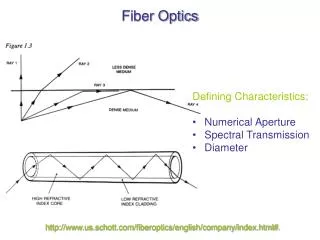
Fiber Optics • The light stays confined to the core because the cladding has a lower refractive index—a measure of its ability to bend light. • The index of refraction of a material is the ratio of the speed of light in vacuum to that of the material. • It is a measure of how much the speed of light slows down after it enters the material.
Fiber Optics • When light goes from one material to another of a different index of refraction, its path will bend, causing an illusion similar to the bent stick stuck into water. • This phenomenon is used to reflect light at the core/cladding boundary of the fiber and trap it in the core
Fiber Optics • The refraction (bending) of light as it passes from air into water causes an optical illusion: objects in the water appear broken or bent at the water’s surface.
Fiber Optics • Total internal refection confines light within optical fibers (similar to looking down a mirror made in the shape of a long paper towel tube).
Fiber Optics • Because the cladding has a lower refractive index, light rays reflect back into the core if they encounter the cladding at a shallow angle (red lines). A ray that exceeds a certain "critical" angle escapes from the fiber (yellow line).
Fiber Optics • Graded-index multimode fiber contains a core in which the refractive index diminishes gradually from the center axis out toward the cladding. • The higher refractive index at the center makes the light rays moving down the axis advance more slowly than those near the cladding.
Fiber Optics • Also, rather than zigzagging off the cladding, light in the core curves helically because of the graded index, reducing its travel distance. • The shortened path and the higher speed allow light at the periphery to arrive at a receiver at about the same time as the slow but straight rays in the core axis. The result: a digital pulse suffers less dispersion
Fiber Optics SINGLE-MODE FIBER: • Has a narrow core (eight microns or less), and the index of refraction between the core and the cladding changes less than it does for multimode fibers.
Fiber Optics • Light thus travels parallel to the axis, creating little pulse dispersion. Telephone and cable television networks install millions of kilometers of this fiber every year.
Fiber Optics • Transmitting data over fiber strands can be accomplished in two ways: LED’s - Light emitting diode LASERS - Light amplification by stimulated emitted radiation
Fiber Optics • Multimode back bones use LED’s to transmit data which make the electronics cost effective • Single mode back bones use LASERS to transmit data which make the electronics considerably more expensive.
Fiber Optics WAVELENGTHS: MULTIMODE850nmand 1310nm SINGLEMODE1300nmand 1550nm • These wave lengths are selected in our fiber testers
Fiber Optics • Information sent over multimode fiber is done with the use of LEDs which actually sends pulses of light that represent on and off conditions or 1s and 0s. • LEDs are one color or wave length and are typically red which can be seen with human eye.
Fiber Optics • Because graded index fiber has many different layers these pulses of light can be sent down each layer which effectively increases its bandwidth. • Single mode fiber utilizes lasers to send information through the optical fiber, this laser light is not visible to the human eye and can be damaging to the eye if looked at directly.
Fiber Optics • Because single mode fiber is step indexed only one laser beam of light is sent down the core, since the core is small and lasers are more powerful than LEDs the light can travel much further. • To increase the bandwidth over single mode different colors of light or different wave lengths are used which actually creates different channels. • Each channel then carries information in the form of 1s and 0s.
Fiber Optics • Each single mode fiber can carry many independent channels, each using a different wavelengths of light which is called wavelength-division multiplexing (WDM). • A vertical cavity surface emitting laser (VCSEL) is a specialized laser diode that is now used in fiber optic communications by improving efficiency and increasing data speed. The acronym VCSEL is pronounced 'vixel.'
Fiber Optics • VSCELs were introduced in the mid 2000s and are used to transmit information over single mode fiber.
Fiber Optics • The VCSEL has several advantages over edge-emitting diodes. • The VCSEL is cheaper to manufacture in quantity, is easier to test, and is more efficient. • In addition, the VCSEL requires less electrical current to produce a given coherent energy output.
Fiber Optics • The VCSEL emits a narrow, more nearly circular beam than traditional edge emitters; this makes it easier to get the energy from the device into an optical fiber. • The main challenge facing engineers today is the development of a high-power VCSEL device with an emission wavelength of 1550 nm.
Fiber Optics • So how much bandwidth can be achieved through a single mode fiber using the latest technologies? • NTT (Nippon Telegraph & Telephone)was able to achieve 69.1 Tbps transmission by applying wavelength division multiplex (WDM) of 432 wavelengths with a capacity of 171 Gbps over a single 240 km-long optical fiber on March 25, 2010. • And then there is…………….
Fiber Optics • In intensive development NEC scientists have managed to reach speed of 101 Tbps by multiplexing 370 channels over a single fiber, while similar Japanese effort reached 109 terabits per second. • But this is barely matching the 50%-per-year exponentially increasing backbone traffic. • 101,000,000,000,000.00bits per second