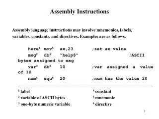
INTREPID 120V Assembly Instructions
This document provides detailed assembly instructions for the Intrepid 120V antenna system. Included are essential components such as three flight cases, user interface unit (UIU), and other attachments. The assembly process is broken down into stages: Tripod setup, Reflector attachment, Motors installation, Feed Arm assembly, and Cabling connections. Each stage outlines the necessary steps and precautions to ensure proper assembly. Follow these instructions carefully for successful deployment of your antenna system.

INTREPID 120V Assembly Instructions
E N D
Presentation Transcript
INTREPID120V Assembly Instructions Version 1.1 – July 08
What Should You Have? • There should be 3 flight cases see below and either • A further cardboard box containing a User Interface Unit (UIU) • Or a further flight case containing the UIU and a Modem
What Should You Have? • The longest Flight Case Contains the main body of the antenna and motors (pictured below) you may need this for re-packing.
Stage 1 – The Tripod • Remove the antenna legs from the flight case and move the feet from the packed position to the operational position • Pull pin as above (1) • Rotate feet into position (2) • Locate pin to lock feet into position (1) (2)
Stage 1 – The Tripod • Open out legs and ensure central stabilizer is firmly seated (see arrow)
Stage 2 – The Reflector • In the second flight case you either have a 6 piece reflector version (1) or a 2 piece reflector version (2) assembly of the Intrepid is identical apart from adding the petals in the 6 piece version. (2) (1)
Stage 2 – The Reflector • Take either the bottom half (2 pc) or the lower centre section (6pc) that has Ipoint controller attached (large white box) • Locate the metal bar on the reverse of the antenna (see arrow) into the channel on the tripod base
Stage 2 – The Reflector • Take the red lever shown below (1) and slide locking plate in place by moving in the direction of the arrow until locked (2) (1) (2)
Stage 2 – The Reflector • Ensure elevation feedback plate is located on locking plate as shown in (1) and not suspended as in (2) a gentle push down will locate (1) (2)
Stage 2 – The Reflector • Attach either the top half of the reflector (2 pc reflector) or the remaining 5 pcs (6 pc reflector) and secure with clips shown below
Stage 3 – The Motors • Allow the reflector assembly move forward a per picture below
Stage 3 – The Motors • Take the Azimuth motor (shorter motor) and locate the lower hole onto the locating pin in the Azimuth (horizontal) motor drive fixing bracket on the tripod shown in below (1) • Locate the clamp bolt (2) and tighten. (1) (2)
Stage 3 – The Motors • Insert motor shaft into pivot point (1) • Insert pin (2) • Lock in position (3) (1) (2) (3)
Stage 3 – The Motors • Insert the Elevation (longer motor) motor shaft into pivot point on the rear of the reflector (1) • Insert pin (2) • Lock in position (3) (1) (2) (3)
Stage 3 – The Motors • Locate Motor in the Elevation Motor Bracket (1) • Locate the 2 clamp bolts one each side (2) and tighten. • Finished assembly shown in (3) (1) (2) (3)
Stage 4 – The Feed Arm • Take the Feed Arm (1) • Locate Feed Arm in the base of the Reflector (2) • Lower Feed Arm gently until located (3) (1) (2) (3)
Stage 4 – The Feed Arm • Take the Feed Arm stabilizer bars and attach onto the feed arm (1) • Attach onto the reflector (2) • Repeat - see both fully fitted (3) (1) (2) (3)
Stage 4 – Pol Assembly • In the third box is the Polarization Assembly (see below)
Stage 4 – Pol Assembly • Take the Pol Assembly slide clip into end of the feed arm (1) • Gently lower the assembly onto the feed arm (2) • Tighten thumbscrew to secure Pol assembly (3) (1) (2) (3)
Stage 5 – Cabling • There are 3 white clips along the feed arm as in picture (1) • Gently push the black Pol cable into the three clips (2) • On the rear of the reflector there are 2 further clips, attach locate the Pol cable & the Azimuth cable (1) (2) (3)
Stage 5 – Cabling • Attach the receive RF cable (1) • Attach the Az motor drive and Feedback connectors (2) • Attach the Pol Motor and Feedback connectors (3) (1) (2) (3)
Stage 5 – Cabling • Attach the Elevation Motor connector (1) • Attach the power connection (right angled connector) (2) • Attach the RS232 connector (3) (1) (2) (3)
Stage 5 – Cabling • The final box contains the UIU (1) • Attach 15 way D-type to the UIU (2) • Ensure 9-Way D-types are connected (3) this is serial connection that can be attached to a PC (1) (2) (3)
Ready to go!! • Place the front leg pointing approximately South • As per the manual you can select a Target and Reference Satellites • Press ENTER when DEPLOY is highlighted on the UIU. • The antenna should lock onto the Target in <3 mins