Download
1 / 25
250 likes | 307 Views
ELECTROSTATICS - IV - Capacitance and Van de Graaff Generator. Behaviour of Conductors in Electrostatic Field Electrical Capacitance Principle of Capacitance Capacitance of a Parallel Plate Capacitor Series and Parallel Combination of Capacitors

E N D
ELECTROSTATICS - IV - Capacitance and Van de Graaff Generator • Behaviour of Conductors in Electrostatic Field • Electrical Capacitance • Principle of Capacitance • Capacitance of a Parallel Plate Capacitor • Series and Parallel Combination of Capacitors • Energy Stored in a Capacitor and Energy Density • Energy Stored in Series and Parallel Combination of Capacitors • Loss of Energy on Sharing Charges Between Two Capacitors • Polar and Non-polar Molecules • Polarization of a Dielectric • Polarizing Vector and Dielectric Strength • Parallel Plate Capacitor with a Dielectric Slab • Van de Graaff Generator Created by C. Mani, Principal, K V No.1, AFS, Jalahalli West, Bangalore
Behaviour of Conductors in the Electrostatic Field: E0 Enet =0 n E EP θ • + q • Net electric field intensity in the interior of a conductor is zero. • When a conductor is placed in an electrostatic field, the charges (free electrons) drift towards the positive plate leaving the + ve core behind. At an equilibrium, the electric field due to the polarisation becomes equal to the applied field. So, the net electrostatic field inside the conductor is zero. • Electric field just outside the charged conductor is perpendicular to the surface of the conductor. • Suppose the electric field is acting at an angle other than 90°, then there will be a component E cos θ acting along the tangent at that point to the surface which will tend to accelerate the charge on the surface leading to ‘surface current’. But there is no surface current in electrostatics. So, θ = 90° and cos 90° = 0. E cos θ NOT POSSIBLE
q ΦE = E . dS= ε0 S q • Net charge in the interior of a conductor is zero. • The charges are temporarily separated. The total charge of the system is zero. Since E = 0 in the interior of the conductor, therefore q = 0. • Charge always resides on the surface of a conductor. • Suppose a conductor is given some excess charge q. Construct a Gaussian surface just inside the conductor. • Since E = 0 in the interior of the conductor, therefore q = 0 inside the conductor. q q = 0 • Electric potential is constant for the entire conductor. • dV = - E . dr Since E = 0 in the interior of the conductor, therefore dV = 0. i.e. V = constant
q q σ = C = S V • Surface charge distribution may be different at different points. σmin σmax Every conductor is an equipotential volume (three- dimensional) rather than just an equipotential surface (two- dimensional). Electrical Capacitance: The measure of the ability of a conductor to store charges is known as capacitance or capacity (old name). q α V or q = C V or If V = 1 volt, then C = q Capacitance of a conductor is defined as the charge required to raise its potential through one unit. SI Unit of capacitance is ‘farad’ (F). Symbol of capacitance: Capacitance is said to be 1 farad when 1 coulomb of charge raises the potential of conductor by 1 volt. Since 1 coulomb is the big amount of charge, the capacitance will be usually in the range of milli farad, micro farad, nano farad or pico farad.
r • O q = V 4πε0 r q C = V C = 4πε0 r Capacitance of an Isolated Spherical Conductor: Let a charge q be given to the sphere which is assumed to be concentrated at the centre. Potential at any point on the surface is +q • Capacitance of a spherical conductor is directly proportional to its radius. • The above equation is true for conducting spheres, hollow or solid. • IF the sphere is in a medium, then C = 4πε0εr r. • Capacitance of the earth is 711 μF.
A B B A E Principle of Capacitance: Step 1: Plate A is positively charged and B is neutral. Step 2: When a neutral plate B is brought near A, charges are induced on B such that the side near A is negative and the other side is positive. The potential of the system of A and B in step 1 and 2 remains the same because the potential due to positive and negative charges on B cancel out. Step 3: When the farther side of B is earthed the positive charges on B get neutralised and B is left only with negative charges. Now, the net potential of the system decreases due to the sum of positive potential on A and negative potential on B. To increase the potential to the same value as was in step 2, an additional amount of charges can be given to plate A. This means, the capacity of storing charges on A increases. The system so formed is called a ‘capacitor’. Potential = V Potential = V Potential decreases to v
σ d V = E d = ε0 E q d V = A ε0 A ε0 d C = q d C = V A ε0 εr C = d Capacitance of Parallel Plate Capacitor: Parallel plate capacitor is an arrangement of two parallel conducting plates of equal area separated by air medium or any other insulating medium such as paper, mica, glass, wood, ceramic, etc. σ σ A A or But If the space between the plates is filled with dielectric medium of relative permittivity εr, then • Capacitance of a parallel plate capacitor is • directly proportional to the area of the plates and • inversely proportional to the distance of separation between them.
Series Combination of Capacitors: V1 V2 V3 V q q q q V = V3 = V2 = V1 = C C3 C1 C2 q 1 1 q q 1 1 q = = + + + + C C C1 C1 C2 C2 C3 C3 n 1 1 ∑ = Ci C i=1 C1 C2 C3 • In series combination, • Charge is same in each capacitor • Potential is distributed in inverse proportion to capacitances q q q i.e. V = V1 + V2 + V3 , , and But (where C is the equivalent capacitance or effective capacitance or net capacitance or total capacitance) or The reciprocal of the effective capacitance is the sum of the reciprocals of the individual capacitances. Note:The effective capacitance in series combination is less than the least of all the individual capacitances.
V n ∑ C = C1 + C2 + C3 = C Ci i=1 Parallel Combination of Capacitors: C1 V q1 • In parallel combination, • Potential is same across each capacitor • Charge is distributed in direct proportion to capacitances C2 q2 V i.e. q = q1 + q2 + q3 C3 q1 = C1 V q2 = C2 V q3 = C3 V and q = C V But , , q3 V C V = C1V + C2 V + C3 V (where C is the equivalent capacitance) or The effective capacitance is the sum of the individual capacitances. Note: The effective capacitance in parallel combination is larger than the largest of all the individual capacitances.
V q dq = C q q q2 1 1 1 dq U = C V2 q V U = U = U = C C 2 2 2 0 Energy Stored in a Capacitor: The process of charging a capacitor is equivalent to transferring charges from one plate to the other of the capacitor. The moment charging starts, there is a potential difference between the plates. Therefore, to transfer charges against the potential difference some work is to be done. This work is stored as electrostatic potential energy in the capacitor. If dq be the charge transferred against the potential difference V, then work done is dU = dW = V dq The total work done ( energy) to transfer charge q is or or or
A ε0 C = d ε0 Ad E2 ε0E2 U = U = Ad 1 1 1 1 1 U ε0E2 = = + ………. + + + C C1 C2 C3 Cn 1 1 1 1 ] [ q2 U = + ………. + + + q2 C1 C2 C3 Cn 1 1 1 1 1 1 C V2 U = U = C 2 2 2 2 2 2 Energy Density: V = E d But and or or SI unit of energy density is J m-3. Energy density is generalised as energy per unit volume of the field. Energy Stored in a Series Combination of Capacitors: U = U1 + U2 + U3 + ………. + Un The total energy stored in the system is the sum of energy stored in the individual capacitors.
( C1 + C2 + C3 + ……….. + Cn ) 1 1 V2 C V2 U = U = C1 V1 + C2 V2 V = 2 2 C1 + C2 Energy Stored in a Parallel Combination of Capacitors: C = C1 + C2 + C3 + ……….. + Cn U = U1 + U2 + U3 + ………. + Un The total energy stored in the system is the sum of energy stored in the individual capacitors. Loss of Energy on Sharing of Charges between the Capacitors in Parallel: Consider two capacitors of capacitances C1, C2, charges q1, q2 and potentials V1,V2. Total charge after sharing = Total charge before sharing (C1 + C2) V = C1 V1 + C2 V2
C1 V12 C2 V22 Ui = + (C1 + C2) V2 Uf = C1 C2 (V1 – V2)2 Ui– Uf = 2 (C1 + C2) 1 1 1 2 2 2 The total energy before sharing is The total energy after sharing is Ui – Uf > 0 or Ui > Uf Therefore, there is some loss of energy when two charged capacitors are connected together. The loss of energy appears as heat and the wire connecting the two capacitors may become hot.
Polar Molecules: 105° p E E = 0 p = 0 p A molecule in which the centre of positive charges does not coincide with the centre of negative charges is called a polar molecule. Polar molecule does not have symmetrical shape. Eg. H Cl, H2 O, N H3, C O2, alcohol, etc. O H H Effect of Electric Field on Polar Molecules: In the absence of external electric field, the permanent dipoles of the molecules orient in random directions and hence the net dipole moment is zero. When electric field is applied, the dipoles orient themselves in a regular fashion and hence dipole moment is induced. Complete allignment is not possible due to thermal agitation.
E p E = 0 p = 0 Non - polar Molecules: A molecule in which the centre of positive charges coincides with the centre of negative charges is called a non-polar molecule. Non-polar molecule has symmetrical shape. Eg. N2 , C H4, O2, C6 H6, etc. Effect of Electric Field on Non-polar Molecules: In the absence of external electric field, the effective positive and negative centres coincide and hence dipole is not formed. When electric field is applied, the positive charges are pushed in the direction of electric field and the electrons are pulled in the direction opposite to the electric field. Due to separation of effective centres of positive and negative charges, dipole is formed.
E = 0 Ep E0 E0 K = E0 - Ep Dielectrics: Generally, a non-conducting medium or insulator is called a ‘dielectric’. Precisely, the non-conducting materials in which induced charges are produced on their faces on the application of electric fields are called dielectrics. Eg. Air, H2, glass, mica, paraffin wax, transformer oil, etc. Polarization of Dielectrics: When a non-polar dielectric slab is subjected to an electric field, dipoles are induced due to separation of effective positive and negative centres. E0 is the applied field and Ep is the induced field in the dielectric. The net field is EN = E0 – Ep i.e. the field is reduced when a dielectric slab is introduced. The dielectric constant is given by
P = n p Polarization Vector: The polarization vector measures the degree of polarization of the dielectric. It is defined as the dipole moment of the unit volume of the polarized dielectric. If n is the number of atoms or molecules per unit volume of the dielectric, then polarization vector is SI unit of polarization vector is C m-2. Dielectric Strength: Dielectric strength is the maximum value of the electric field intensity that can be applied to the dielectric without its electric break down. Its SI unit is V m-1. Its practical unit is kV mm-1.
Capacitance of Parallel Plate Capacitor with Dielectric Slab: E0 K = t d EN σ E0 E0 = EN = ε0 K E0 t t V = E0 (d – t) + q K A ε0 C = K ] V = E0[ (d – t) + C = V E0 Ep d [1 – t (1 - t ) ] d K qA = ε0 C0 A ε0 C = C = [1 – t (1 - t t ) ] ] [ (d – t) + d K K V = E0 (d – t) + EN t or EN = E0 - Ep or But and or C > C0. i.e. Capacitance increases with introduction of dielectric slab.
C K = C = K C0 C0 If the dielectric slab occupies the whole space between the plates, i.e. t = d, then Dielectric Constant WITH DIELECTRIC SLAB
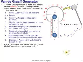
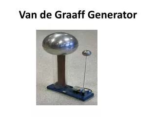
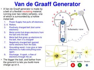
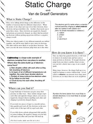
HVR Van de Graaff Generator: S P2 C2 S – Large Copper sphere C1, C2 – Combs with sharp points P1, P2 – Pulleys to run belt HVR – High Voltage Rectifier M – Motor IS – Insulating Stand D – Gas Discharge Tube T - Target D T C1 I S P1 M
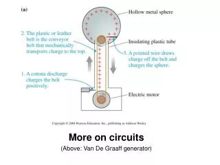
Principle: Consider two charged conducting spherical shells such that one is smaller and the other is larger. When the smaller one is kept inside the larger one and connected together, charge from the smaller one is transferred to larger shell irrespective of the higher potential of the larger shell.i.e. The charge resides on the outer surface of the outer shell and the potential of the outer shell increases considerably. Sharp pointed surfaces of a conductor have large surface charge densities and hence the electric field created by them is very high compared to the dielectric strength of the dielectric (air). Therefore air surrounding these conductors get ionized and the like charges are repelled by the charged pointed conductors causing discharging action known as Corona Discharge or Action of Points. The sprayed charges moving with high speed cause electric wind. Opposite charges are induced on the teeth of collecting comb (conductor) and again opposite charges are induced on the outer surface of the collecting sphere (Dome).
Construction: Van de Graaff Generator consists of a large (about a few metres in radius) copper spherical shell (S) supported on an insulating stand (IS) which is of several metres high above the ground. A belt made of insulating fabric (silk, rubber, etc.) is made to run over the pulleys (P1, P2 ) operated by an electric motor (M) such that it ascends on the side of the combs. Comb (C1) near the lower pulley is connected to High Voltage Rectifier (HVR) whose other end is earthed. Comb (C2) near the upper pulley is connected to the sphere S through a conducting rod. A tube (T) with the charged particles to be accelerated at its top and the target at the bottom is placed as shown in the figure. The bottom end of the tube is earthed for maintaining lower potential. To avoid the leakage of charges from the sphere, the generator is enclosed in the steel tank filled with air or nitrogen at very high pressure (15 atmospheres).
Working: Let the positive terminal of the High Voltage Rectifier (HVR) is connected to the comb (C1). Due to action of points, electric wind is caused and the positive charges are sprayed on to the belt (silk or rubber). The belt made ascending by electric motor (EM) and pulley (P1) carries these charges in the upward direction. The comb (C2) is induced with the negative charges which are carried by conduction to inner surface of the collecting sphere (dome) S through a metallic wire which in turn induces positive charges on the outer surface of the dome. The comb (C2) being negatively charged causes electric wind by spraying negative charges due to action of points which neutralize the positive charges on the belt. Therefore the belt does not carry any charge back while descending. (Thus the principle of conservation of charge is obeyed.) Contd..
The process continues for a longer time to store more and more charges on the sphere and the potential of the sphere increases considerably. When the charge on the sphere is very high, the leakage of charges due to ionization of surrounding air also increases. Maximum potential occurs when the rate of charge carried in by the belt is equal to the rate at which charge leaks from the shell due to ionization of air. Now, if the positively charged particles which are to be accelerated are kept at the top of the tube T, they get accelerated due to difference in potential (the lower end of the tube is connected to the earth and hence at the lower potential) and are made to hit the target for causing nuclear reactions, etc.
Uses: • Van de Graaff Generator is used to produce very high potential difference (of the order of several million volts) for accelerating charged particles. • The beam of accelerated charged particles are used to trigger nuclear reactions. • The beam is used to break atoms for various experiments in Physics. • In medicine, such beams are used to treat cancer. • It is used for research purposes. END OF ELECTROSTATICS