Download
1 / 11
110 likes | 382 Views
Explore the evolution of electrolytic capacitors using materials like activated carbon and carbon nanotubes. Learn about the differences between batteries & supercapacitors, focusing on power density, energy density, and environmental impact.

E N D
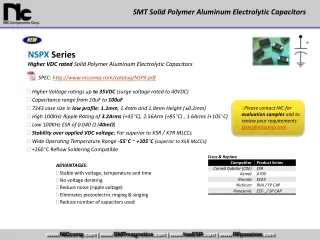
Double Layer Electrolytic Capacitors Design Team 10 Technical Lecture ECE_480_FS08
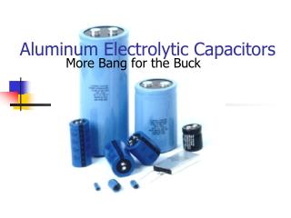
Electrolytic Capacitors • Two parallel plates with dielectric in between • Capacitance limited by flat surface area and dielectric properties • C is the capacitance • A is the area • εr is the relative static permittivity (dielectric constant) • εo is the permittivity of free space (8.854x10⁻¹² F/m) • d is distance
Carbon Aerogel -Aerogel is a low-density solid derived from gel that has had the liquid component replaced with a gas. • Composed of nanometer sized particles covalently bonded together • High porosity (>50% under 100 nm) • Large surface area (400–1000 m²/g)
Activated Carbon: • Extremely porous with a very large surface area. • Surface resembles a sponge. • Area allows more electrons to be stored than other conductors. Activated Carbon ( Activated Charcoal )
Double Layer Electrolytic CapacitorsUsing Activated Carbon • Two layers consisting of nanoporous electrodes • Separator is impregnated with an organic electrolyte • Thin separator can only withstand low voltages
Carbon Nanotubes • Approximately 1/50,000th the width of a human hair • Strongest and stiffest material on earth (>300 X Steel) • Low density • Semiconductor
Double Layer Electrolytic Capacitors Using Carbon Nanotubes • Under development at MIT • Replaces activated charcoal with carbon nanotubes • Aligned in a regular pattern that exposes greater surface area • Dramatically increases effective area of electrodes • Greatly increases power density
Comparing Batteries & Supercapacitors • Energy density is the amount of energy stored per unit volume or mass. • Power density combines energy density with the speed that • energy can be drawn out of a device.
Rechargeable Batteries Vs. Supercapacitors Supercapacitors: • Higher power density • Much faster charge and discharge rate • Environmentally friendly • Extremely low internal resistance or ESR • High efficiency (97-98%) • Over a million charge-discharge cycles Batteries: • Have higher energy density • Typically 200–1000 charge-discharge cycles • Contain highly reactive and hazardous chemicals • Negatively affected by low temperatures
Applications for Supercapacitors • Back up for uninterruptable power supplies (UPS) • Light weight power supplies for small aircraft • Provide short duration power for various vehicle systems such as braking or steering • Used to absorb power during short periods of generation such as Regenerative Braking • Extend range and battery life in Hybrid Electric Vehicles (HEV)
Hybrid Electric Vehicles • The CSIRO in Australia [national science agency] has developed the UltraBattery, which combines a supercapacitor and a lead acid battery in a single unit • 4x longer life cycle, 50% more power, 70% cheaper than batteries used in HEV’s