Download

1 / 16
750 likes | 1.86k Views
Op-Amps. Microprocessor Interface. Operational Amplifier (Op-Amp). Very high differential gain High input impedance Low output impedance Provide voltage changes (amplitude and polarity) Used in oscillator, filter and instrumentation Accumulate a very high gain by multiple stages.

E N D
Op-Amps Microprocessor Interface
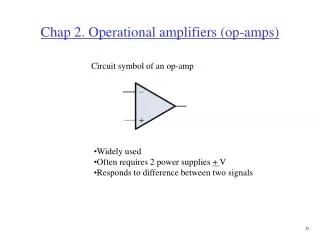
Operational Amplifier (Op-Amp) • Very high differential gain • High input impedance • Low output impedance • Provide voltage changes (amplitude and polarity) • Used in oscillator, filter and instrumentation • Accumulate a very high gain by multiple stages
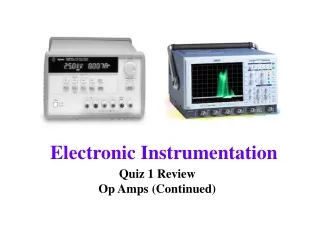
IC Product DIP-741 Dual op-amp 1458 device
Distortion The output voltage never excess the DC voltage supply of the Op-Amp
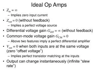
Op-Amp Properties • Infinite Open Loop gain • The gain without feedback • Equal to differential gain • Zero common-mode gain • Pratically, Gd = 20,000 to 200,000 • (2) Infinite Input impedance • Input current ii ~0A • T- in high-grade op-amp • m-A input current in low-grade op-amp • (3) Zero Output Impedance • act as perfect internal voltage source • No internal resistance • Output impedance in series with load • Reducing output voltage to the load • Practically, Rout ~ 20-100
Frequency-Gain Relation • Ideally, signals are amplified from DC to the highest AC frequency • Practically, bandwidth is limited • 741 family op-amp have an limit bandwidth of few KHz. 20log(0.707)=3dB • Unity Gain frequency f1: the gain at unity • Cutoff frequency fc: the gain drop by 3dB from dc gain Gd GB Product : f1 = Gdfc
? Hz 10MHz GainBandwidth Product Example: Determine the cutoff frequency of an op-amp having a unit gain frequency f1 = 10 MHz and voltage differential gain Gd = 20V/mV • Sol: • Since f1 = 10 MHz • By using GB production equation • f1 = Gdfc • fc = f1 / Gd = 10 MHz / 20 V/mV • = 10 106 / 20 103 • = 500 Hz
Ideal Op-Amp Applications • Analysis Method : • Two ideal Op-Amp Properties: • The voltage between V+ and V is zero V+ = V • The current into both V+ and V termainals is zero • For ideal Op-Amp circuit: • Write the kirchhoff node equation at the noninverting terminal V+ • Write the kirchhoff node eqaution at the inverting terminal V • Set V+ = V and solve for the desired closed-loop gain
Noninverting Amplifier • Kirchhoff node equation at V+ yields, • Kirchhoff node equation at Vyields, • Setting V+ = V– yields • or
Noninverting amplifier Noninverting input with voltage divider Less than unity gain Voltage follower
Inverting Amplifier • Kirchhoff node equation at V+ yields, • Kirchhoff node equation at Vyields, • Setting V+ = V– yields Notice: The closed-loop gainVo/Vin is dependent upon the ratio of two resistors, and is independent of the open-loop gain. This is caused by the use of feedback output voltage to subtract from the input voltage.
Multiple Inputs • Kirchhoff node equation at V+ yields, • Kirchhoff node equation at Vyields, • Setting V+ = V– yields
Inverting Integrator • Now replace resistors Ra and Rf by complex components Za and Zf, respectively, therefore • Supposing • The feedback component is a capacitor C, i.e., • The input component is a resistor R, Za = R • Therefore, the closed-loop gain (Vo/Vin) become: • where • What happens if Za = 1/jC whereas, Zf = R • Inverting differentiator
Op-Amp Integrator • Example: • Determine the rate of change • of the output voltage. • Draw the output waveform. Solution: (a) Rate of change of the output voltage (b) In 100 s, the voltage decrease
Slew Rate The maximum possible rate at which an amplifier’s output voltage can change, in volts per second, is called its slew rate. FIGURE 10-17 The rate of change of a linear, or ramp, signal is the change in voltage divided by the change in time