Download
1 / 61
1.03k likes | 2.14k Views
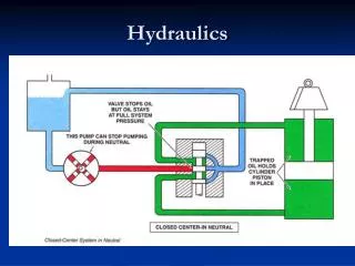
HYDRAULICS & PNEUMATICS. Actuators. Presented by: Dr. Abootorabi. Hydraulic Cylinders. Actuators are the components used in a hydraulic system to provide power to a required work location .

E N D
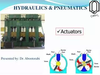
HYDRAULICS & PNEUMATICS • Actuators Presented by: Dr. Abootorabi
Hydraulic Cylinders • Actuators are the components used in a hydraulic system to provide power to a required work location. • Cylinders are the hydraulic system components that convert fluid pressure and flow into linear mechanical force and movement.
Hydraulic Cylinders • A basic cylinder consists of: • Piston • Piston rod • Barrel • The piston forms sealed, variable-volume chambers in the cylinder. • System fluid forced into the chambers, drives the piston and rod assembly.
Hydraulic Cylinders • Seals prevent leakage between: • Piston and cylinder barrel • Piston rod and head • Barrel and its end pieces • Wiper seal, or scraper, prevents dirt and water from entering the cylinder during rod retraction.
Hydraulic Cylinders • Various seals are used in a cylinder
Hydraulic Cylinders • Various seals are used in a cylinder
Hydraulic Cylinders • Various seals are used in a cylinder
Hydraulic Cylinders • Cylinders are typically classified by operating principle: • Single-acting • Double-acting Single-acting Double-acting
Hydraulic Cylinders • Single-acting cylinder exert force either on extension or retraction: • They require an outside force to complete the second motion (either by a spring or by the weight load). • Double-acting cylinder generate force during both extension and retraction: • Directional control valve alternately directs fluid to opposite sides of the piston • Force output varies between extension and retraction
Hydraulic Cylinders • Single-acting cylinder • hydraulic ram (or plunger cylinder): piston and rod form one unit
Hydraulic Cylinders • Single-acting cylinder Scissor lifting table:
Hydraulic Cylinders • Double-acting cylinder
Hydraulic Cylinders • Double-acting cylinder types:
Hydraulic Cylinders • Double-acting cylinder types:
Hydraulic Cylinders • Effective piston area is reduced on retraction due to the rod cross section.
Hydraulic Cylinders • Telescoping cylinders are available for applications requiring long extension distances: • Rod is made up of several tubes of varying size nested inside of the barrel • Each tube extends, producing a rod longer than the cylinder barrel • Typical example is the actuator that raises the box on a dump truck
Hydraulic Cylinders • Telescoping cylinders: • The maximum force is at the collapsed position • The speed will increase at each stage, but will not allow much force
Hydraulic Cylinders • Cylinders often use hydraulic cushions (to brake high stroke speeds): • Provide a controlled approach to the end of the stroke • Reduces the shock of the impact as the piston contacts the cylinder head
Hydraulic Cylinders • Cylinders with end position cushioning: • Cushioning is not required for speeds of v<6 m/min. • This type of end position cushioning is used for stroke speed between 6 m/min and 20 m/min. At higher speed, additional cushioning or braking devices must be used.
Hydraulic Cylinders • A variety of mounting configurations are used to attach the cylinder body and rod end to machinery: • Fixed centerline • Fixed noncenterline • Pivoting centerline • Expected cylinder loading is the major factor in the selection of the mounting style.
Hydraulic Cylinders • Head-end (Fixed centerline) flange mount
Hydraulic Cylinders • Fixed-noncenterline mount
Hydraulic Cylinders • Pivoting-centerline, clevis mount
Hydraulic Cylinders • Pivoting-centerline, trunnion mount
Hydraulic Cylinders • Types of mounting:
Hydraulic Cylinders • The force generated by a cylinder is calculated by multiplying the effective area of the piston by the system pressure. • F=p.A • By consideration of mechanical efficiency:
Hydraulic Cylinders • Cylinder characteristics
Hydraulic Cylinders • Cylinder characteristics dp: cylinder dia. Ap: cylinder area dST: piston rod dia.
Effective area Piston velocity Hydraulic Cylinders • Speed at which the cylinder extends or retracts is determined by: • Flow Rate (Q) • Effective Area (A) Q [m3/s] = A [m2] X [m/s]
Hydraulic Cylinders • Buckling resistance
Hydraulic Cylinders • Selecting a cylinder (Example)
Hydraulic Cylinders • Selecting a cylinder (Example)
Hydraulic Cylinders • Selecting a cylinder (Example) Buckling resistance diagram: Reference: Festo Didactic Hydraulic
Hydraulic Cylinders • Selecting a cylinder (Example)
Hydraulic Cylinders • Selecting a cylinder (Example)
Hydraulic Cylinders • Selecting a cylinder (Example)
Hydraulic Cylinders • Hydraulic cylinder manufacturers provide detailed specifications and basic factors such as: • Bore • Stroke • Pressure rating • Other details, such as service rating, rod end configurations, and dimensions
Hydraulic Cylinders • Typical manufacturer’s catalog page Bailey International Corporation
Limited-Rotation Hydraulic Actuators • Limited-rotation devices (swivel drive) are actuators with an output shaft that typically applies torque through approximately 360° of rotation. • Models are available that are limited to less than one revolution, while others may produce several revolutions.
Limited-Rotation Hydraulic Actuators • Most common designs of limited-rotation actuators are: • Rack-and-pinion • Vane • Helical piston and rod
Limited-Rotation Hydraulic Actuators • Rack-and-pinion limited rotation actuator • Here maximum angle may be larger than 360°.
Limited-Rotation Hydraulic Actuators • Vane limited-rotation actuator
Limited-Rotation Hydraulic Actuators • Helical piston and rod limited-rotation actuator
Limited-Rotation Hydraulic Actuators • Limited-rotation actuators are used to perform a number of functions in a variety of industrial situations: • Indexing devices on machine tools • Clamping of workpieces • Operation of large valves • Limited-rotation actuators are used in this robotic arm:
Hydraulic Motors • Hydraulic motors are called rotary actuators. • They convert fluid pressure and flow into torque and rotational movement.
Hydraulic Motors • System fluid enters the housing and applies pressure to the rotating internal parts. • This, in turn, moves the power output shaft and applies torque to rotate a load. • Primary parts that produce the rotating motion in most hydraulic motors are either: • Gears • Vanes • Pistons
Hydraulic Motors • The external gear hydraulic motor is the most common and simplest of the basic motor types: • Unbalanced load on the bearings
Hydraulic Motors • The most common internal gear motor has a gerotor design
Hydraulic Motors • Basic vane motor (unbalanced)
Hydraulic Motors • A basic, balanced vane motor