Download

1 / 29
310 likes | 971 Views
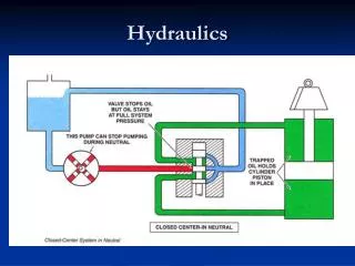
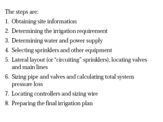
Pipeline Hydraulics. Importance. Irrigation hydraulics involves: The determination of the pressure distribution in the system The selection of pipe sizes and fittings to convey and regulate water delivery The determination of the power and energy requirements to pressurize and lift water.

E N D
Importance Irrigation hydraulics involves: • The determination of the pressure distribution in the system • The selection of pipe sizes and fittings to convey and regulate water delivery • The determination of the power and energy requirements to pressurize and lift water
Basic Relationships • Q = Vm Af • Flow rate = (velocity) x (cross-sectional area) • Called the continuity equation • Units must be consistent • Maximum recommended V in a pipeline is about 5 feet/second
Energy • Forms of energy available in water • Kinetic energy due to velocity • Potential energy due to elevation • Potential energy due to pressure
Units • Energy per unit weight of water = "head“ Energy (ft-lb)/Weight (lb) = Head (ft) • Velocity head; Elevation head; Pressure head • Length units (e.g., feet, meters)
Velocity Head • Velocity head = • g = gravitational constant = 32.2 ft/s2 • when V is 5 ft/s, V2/(2g) is only about 0.4 ft (usually negligible)
Elevation Head • Elevation head (gravitational head) = Z • Height of water above some arbitrary reference point (datum) • Water at a higher elevation has more potential energy than water at a lower elevation
Pressure Head • Pressure = force per unit area (e.g., pounds per square inch) • Pressure head = pressure per unit weight of water • h = P / • h = pressure head , P = pressure • = weight of a unit volume of water • = 62.4 lb/ft3 = 0.433 psi/ft • 1/ = 2.31ft/psi • h = 2.31*P (P is in psi; h in ft)
Calculate P at the Bottom of a Column of Water When depth of 2 ft is considered V = 2 ft3 W = 2 ft3 * 62.4 lb/ft3 = 124.8 lb A = 144 in2 P = W/A = 124.8lb / 144 in2 = 0.866 lb/in2 If depth is 1ft then V = 1 ft3 W = 62.4lb P = 62.4lb/144in2 = 0.433lb/in2
Calculate P at the Bottom of a Column of Water V = 2 ft3 W = 124.8 lb A = 2ft2 = 288 in2 P = 124.8lb / 288in2 = 0.433 lb/in2 The area of a pond or tank does not affect pressure. Pressure is a function of water depth only.
Manometer Rising up From a Pipeline Pressure, P = lb/ft2 γ = specific weight of water, (62.4 lb/ft3) H=P/g
hydraulic head, H = • Bernoulli’s equation (conservation of energy) • H1 = H2 + hL • H1 = hydraulic head at point 1 in a system • H2 = hydraulic head at point 2 in a system • hL= head loss during flow from point 1 to point 2 (hL is due to friction loss)
Components of Hydraulic Head for Pipeline With Various Orientations hL
Components of Hydraulic Head for Pipeline With Various Orientations Contd… hL
Components of Hydraulic Head for Pipeline With Various Orientations Contd… hL
Friction Loss • Description: • energy loss due to flow resistance as a fluid moves in a pipeline • Factors affecting • flow rate • pipe diameter • pipe length • pipe roughness • type of fluid
Ways of Calculating Friction Loss • Equations • Hazen-Williams is one of many (eq’n 8.8) • Tables • for a given pipe material, pipe diameter, and flow rate, look up values for friction loss in feet per hundred feet of pipe • SDR = standard dimension ratio = pipe diameter wall thickness
Dimensional Comparison of Sch. 40, Class 160, and Class 125 PVC Pipe
Friction Loss for IPS PVC Pipe IPS: Iron Pipe Size (same dimensions as steel pipe of same nominal size)
Example Problem A 4-inch nominal diameter PVC pipe has a outside diameter of 4.5 inches and a wall thickness of 0.173 inches. What is the pipe SDR? Solution: SDR = Diameter/Wall Thickness SDR = 4.50/0.173 = 26.0
Pipes With Multiple Outlets • lower friction loss because V decreases with distance down the pipe (Q decreases as flow is lost through the outlets; V=Q/A) • first calculate friction loss as if there were no outlets, and then multiply by the "multiple outlet factor", F
Multiple Outlet Factors for Laterals With Equally Spaced Outlets of the Same Discharge
Example Problem A 2-inch diameter, SDR 21 PVC pipe carries a flow of 60 gpm. The flow is discharged through 15 sprinklers evenly spread along its 600-ft length. What is the total head loss in the pipe? Solution: Hf = 4.62 ft / 100 ft (Table 8.2) Hf = 4.62 * 600 ft / 100 ft = 27.72 ft F = 0.379 (Table 8.3; 15 outlets) Hf = 27.72 ft * 0.379 = 10.51 ft
“Minor” Losses • Source of minor losses • fittings, valves, bends, elbows, etc • friction, turbulence, change in flow direction, etc • hm = head loss in fitting (ft) • K = resistance coefficient for fitting
Resistance Coefficient H for Use Determining Head Losses in Fittings and Valves
Calculation Shortcuts • V in ft/s • Q in gpm • D in inches (INSIDE diameter) • hm in ft • Q in gpm • D in inches (INSIDE diameter)
Example Problem A 4-inch pipe carries a flow of 160 gpm. How much head loss occurs when the flow passes through a 90o elbow (flanged, regular radius) ? Solution: K = 0.31 (Table 8.4: 4-in, regular 90o elbow) D = 4.0 inches