Download
1 / 19
210 likes | 316 Views
This study explores the bulk micromachining of silicon for high aspect-ratio structures, porous silicon growth on proton-implanted silicon, and experimental results of proton beam irradiation. Applications include MEMS and IC packaging.

E N D
BulkMicromachiningdelsiliciomedianteimpiantazione di protoni Comunicazione ENEA C.R. Frascati – UTAPRAD-SOR Nenzi P., Fastelli A., Gallerano G., Marracino F., Picardi L., Ronsivalle C. ENEA C.R. Casaccia – UTRINN-FVC Tucci M. Sapienza Università di Roma –DIET Balucani M., Klishko A. 100° Congresso Nazionale – Società Italiana di Fisica – Pisa – 25/09/2014
Outline • Bulk micromachining of silicon • MEMS and Advanced IC packaging applications • Porous silicon based micromachining • Porous Silicon growth on proton implanted silicon • Uniform proton beam irradiation of silicon samples • TOP-IMPLART Proton LINAC • Experimental results • Conclusions
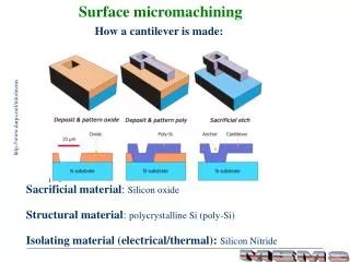
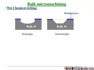
Bulk Micromachining of Silicon Bulk micromachining: realization of high aspect-ratio structures in the bulk of a silicon wafer. • Applications: • MEMS (Micro-Electro-Mechanical-Systems) • IC Packaging (Silicon Interposers)
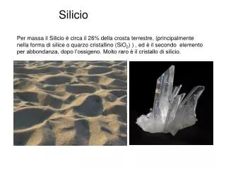
Porous Silicon • Porous silicon (PS or PSi) has been discovered in 1956 at Bell Labs by A. Uhlir and I. Uhlir and later rediscovered in the ’90 because of its photoluminescence properties. Nano-porous silicon from n+ silicon Macro-porous silicon from p- silicon Pore Silicon Nanocrystals
Porous Silicon Reference Card Effect of anodization parameters on PSi (1nm/s per 1mA/cm2) Ultimate Strength (Balucani) Critical parameters Model: Dielectric function of PSi (effective medium approximation) Thermal conductivity (MesoPS) ε: Si permittivity, εeff: effective permittivity, εM: permittivity of host material (air), P: porosity IUPAC classification
Porous silicon for bulk micromachining • In bulk micromachiningapplicationsporoussiliconisusedas a scarificiallayerthatisetchedawayto reveal the structure. • Extremely high selectivity of PS etching in comparison with bulk Si. Etchingratioof PS to Si is 100000:1! • PS layers can be selectivelyetched by means of the structure sensitive mechanism. TSV structures filled with Cu formed from ordered macro PS (P. Nenzi et al., ECTC 2013) High aspect ratio macro-pores, random order (M. Balucani, 2010)
Experiments on Porous silicon growth on Proton IMPLANTATED SILICON
Porous silicon growth suppression over irradiated areas • Damage profile for protons with energy of 250 keV • Damage profile almost constant for the first 2.2 mm (below surface) • Tenfold (10x) defect density increase at the at the stopping range. Low defect region • The lateral electric field generated by implanted protons in the damaged regions causes a deflection of holes. • Deflection increases near the highly defective region, corresponding to the stopping range. • Hole current bends over the highly defective region. • Porous silicon growth is suppressed only in the highly defective region at low doses (<1014 /cm2). • Porous silicon growth is suppressed along all the particles path for high dose (>1014/cm2). High defect region surface Defect density Electric field distribution with increasing dose 1 Depth(um) 2 3 Low dose High dose M. B. H. Breese at al., Phys. Rev B 73, 035428 2006
Porous silicon growth suppression over irradiated areas E. J. Teo et al., Opt. Express 16 (2) 573-578
TOP – IMPLART experiment on Uniform PROTON BEAM irradiation of silicon samples
TOP-IMPLART proton LINAC • TOP-IMPLART project is aimed to the development of a proton LINAC for Hadron therapy using compact S-band accelerating sections (SCDTL) • The LINAC is under construction at ENEA C.R. Frascati by the UTAPRAD Unit • The machine is now capable of delivering a pulsed proton beam with energies up to 11.6 MeV • Lower energy beams can be obtained on a vertical line (radiobiology) or by degrading the energy of the main beam line VERTICAL LINE TERMINAL VARIABLE CURRENT 30keV SOURCE 3 – 7 MeV RFQ DTL HORIZONTAL LINE EXTRACTIONS
Experimental setup • Silicon sample is masked with a 200μm thick molybdenum mask • Silicon sample and mask are mounted on a custom designed holder and installed at the end of the accelerator pipe. • Beam current and sample temperature have been recorded during the processes
Experimental Conditions • Target implantation depth: 30μm • Target fluence: 1e15/cm2 • Beam current: 95μA per pulse • Exposure time: 75 min (4500 s) • Substrate type: p- (100), 10 Ohm*cm, B doped • SRIM/TRIM code has been used to compute energy • Accelerator minimum energy is 3MeV so an aluminum energy degrader (60μm thick) has been placed between the beam and the target to reduce it to 1.3MeV H+ 3 MeV 60 µm Al 45 µm Si Pulse width 80μs, PRF=30 Hz. Maximum temp. on sample 150 °C.
Expected results Etching time Irradiated Si core • We expect an increment in silicon resistivity of the implanted area (near stopping range) due to interaction with Boron dopant counteracting its electrical activity (neutralization). • The presence of hydrogen in p-type semiconductor leads to the formation of the H+ donor, that neutralizes ionized impurities. • Growth of porous silicon is suppressed on those high resistivity areas.
Conclusions • TOP-IMPLART proton linear accelerator has been used to test uniform beam irradiation of silicon samples for potential applications to silicon bulk micromachining (MEMS, Advanced IC Packaging) • New experiments will be carried on in 2014 and 2015 to investigate the benefits and limit of TOP-IMPLART LINAC use for semiconductor processing • When energies higher than 11.6 MeV will be reached (next LINAC section) activities on the qualification of electronics components are planned Current Experiments TOP-IMPLART capability