Download
1 / 16
160 likes | 188 Views
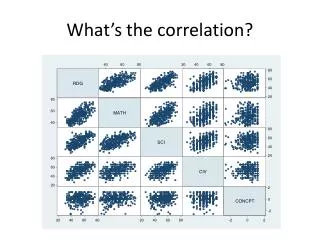
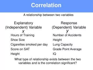
Explore the technical coordination meeting where the Murchison Widefield Array (MWA) introduction revealed the design specifics of the correlator system for processing dual polarization beams in the low-frequency array in the Australian outback.

E N D
Correlation in the MWA US VLBI Technical Coordination Meeting Roger Cappallo 2007.5.14
MWA Introduction • Low frequency (80-300 MHz) array in outback of Western Australia • 500 dual pol. dipole tiles spread across 1.5 km of desert • Analog signals sampled at 640 MHz, broken into coarse (~1.3 MHz) channels, of which 31 MHz are transmitted to correlator
coarseF fineF PFB: fine channels, reorder, route X, short med sum rotate, long sum
Large-N Considerations • Correlator design based on ideas developed independently at CSIRO and MIT • Joint white paper (Bunton, Cappallo, Morales, 2005) applying ideas to SKAMP and MWA • Large N correlator has two central problems: computation and routing • How to bring >500K signal pairs together for multiply and add? • Answer: Replicate (500x!) signals at as low a level as possible, in hierarchical fashion
Signal Replication • In order of increasing cost: • local traces in FPGA (x16) • chip-wide traces in FPGA (x8) • multiple traces on PC board (x4) • across a backplane • off-board signals (e.g. multicast packets)
Temporal Mismatch • FPGA multiplier rate ~250 MHz • Data sample rate is 10 KHz • Factor of 25000 mismatch! • Answer: Time multiplex over multiple (256) station pairs, and multiple (96) frequency channels
Correlator Requirements • Complex cross-multiply and accumulate data from 524800 signal pairs • Each pair comprises 3072 channels with 10 KHz bandwidth • 10 KHz bandwidth 30 Km wavelength, thus array is / 20 within a channel, regardless of direction! • Max fringe-rate of 0.109 Hz for 1.5 km baseline at 300 MHz would allow dump rate of 2 s (which is v.1 int. period); 0.5 s used for solar & transients, longer baselines, minimize coherence loss • No fringe rotation or delay compensation necessary in hardware!
System Dataflow
Numerology • 1 correlator board has 8 SX-35’s, each with 136 cells, which can process a total of 278528 signal pairs • Each pair of correlator boards processes 96 channels (0.967 MHz) • 32 board pairs required for all 3072 channels (30.94 MHz) • Requires five 23” or six19” AdvancedTCA shelves
Two boards cover all baselines • 2boards: m andn • CMACchips 0..7 • axis of symmetry along hypotenuse • reverse input order to get lower diagonal half
Cells mapped onto SX-35 chip • Separate groups of 256 antennas to X and to Y • Uses 136 of 192 available DSP slices
Correlator cell • 16 X & 16 Y 8 bit input values in distributed RAM, for a single point in time • complex 4+4 bit multiply encoded into single 36 bit hardware multiply • 18 bit adder implemented in local fabric • short-term sums ping pong in block RAM: 2 comp x 18 bit x 256 prod x 2 buffers = 18 Kb
Data Ordering - tnf96t512a1024 • Within a cell 2 sets of 16 antenna samples for each time point are cross multiplied and added into 256 short term accumulators • Process is repeated for 512 t points, when accum is dumped to LTA and cleared • Above done for each of 96 channels, then repeated for next time block, etc.
Voltage Beamformer • Not needed for 32T system, so detailed development has not yet begun • For each frequency channel, need to form a linear combination of all 1024 antennas: V = an x gn • 16 dual polarization beams are formed (but treated internally as 32 single polarization beams) • Computational load ~1.0 TCMAC/s • only 6% of correlator load of 16.2 TCMAC/s • possibly will be done in routing chips (FX-20’s)
Beamformer Gains • If every beam, baseline, and channel gain were independently specified, it would require 1 TB/s of coefficient data! But… • Complex gains gn are a product of • instrumental gain - slow t variation, gi(,) • ionospheric phase - medium t variation, gs(,), f-2 freq dependence • geometric phase - rapid f variation (linear), gg(,) • Gain flow from RTS to beamformer must be efficient, taking advantage of characteristics of each term • e.g. geometric phase could be specified as 2 numbers: phase at low f end, and increment per channel