Download
1 / 2
20 likes | 181 Views
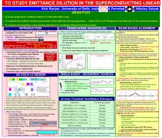
TO STUDY EMITTANCE DILUTION IN THE SUPERCONDUCTING LINEAR. Kirti Ranjan, University of Delhi, India & Fermilab ; Nikolay Solyak. OBJECTIVES To study single-bunch emittance dilution in USColdLC Main Linac

E N D
TO STUDY EMITTANCE DILUTION IN THE SUPERCONDUCTING LINEAR Kirti Ranjan, University of Delhi, India & Fermilab ; Nikolay Solyak • OBJECTIVES • To study single-bunch emittance dilution in USColdLC Main Linac • To compare the emittance dilution performance of two different steering algorithms : “One-to-One” and “Dispersion Free Steering” for the nominal conditions • To compare the sensitivity of the steering algorithms for conditions different from the nominal • USColdLC Main linac will accelerate e-/e+ from~5 GeV-> 250 GeV • Adaptation from the TESLA TDR • Two major design issues: • ENERGY : Efficient acceleration of the beams • LUMINOSITY : Emittance preservation • Vertical plane would be more challenging: • Large aspect ratio (x:y) in both spot size and emittance (400:1) • ~ 2-3 orders of magnitude more difficult • Primary sources of Emittance Dilution: • Transverse Wakefields (Beam Break Up): • Short Range : misaligned structures or cryomodules (CM) • Long Range : as above, and also beam jitter • Dispersion from Misaligned Quads or Pitched Structures • XY-coupling from rotated Quads • Transverse Jitter driven by Quad vibration BEAM BASED ALIGNMENT TRANSVERSE WAKEFIELDS INTRODUCTION • Alignment tolerances can not be met by ab initio installation • Beam line elements are needed to be aligned with beam-based measurements • “Beam Based Alignments (BBA)” refer to the techniques which provide information on beamline elements using measurements with the beam • Quad strength variation • “One-to-One” Correction • Dispersion Free Steering • Dispersion bumps, Ballistic Alignment, others… • When a bunch travels through a structure with transverse offset w.r.t. the structure axis, bunch induces transverse wakefields • Act back on the beam itself • Transverse and Longitudinal • Short & Long range • SC advantage : scales as ~a4 & ~f3 Misaligned Cavity Normalized Emittance Dilution Budget DR Exit =>ML Injection=>ML Exit=>IP TESLA (TDR):Hor./Vert (nm-rad): 8000 /20=>10000 / 30 USColdLC: Hor./Vert (nm-rad): 8000 / 20 => 8800 / 24=>9200 / 34=>9600 / 40 Banana Effect • Single Bunch • Short Range Transverse wakes are very weak • Causes very small emittance dilution as compared to Dispersion Estimate beam-to-quad offset Considered here • Quad Shunting:Measure beam kick vs quad strength to determine BPM-to-Quad offset (prerequisite, routinely done) 10 nm (50%) Vertical emit. Growth in USColdLC Emittance dilution with only RF structure misalignments New tr. wakes ~ 30% less • Allows estimation of beam-to-quad offset • In USColdLC, it is not assumed that all quads would be shunted • Quads are Superconducting and shunting might take long time • No experimental basis for estimating the stability of the Magnetic center as a function of excitation current in SC magnets • In Launch region (1st 7 Quads), we assume that offsets would be measured and corrected with greater accuracy (~30 mm) New wake calculations from Zagorodnov & Weiland 2003 SINGLE BUNCH – INCOHERENT SOURCES US COLD LC DESIGN • One-to-One (1-2-1):Every linac quad contains a cavity Q-BPM (with fixed transverse position) • Quad alignment – How to do? • Find a set of BPM Readings for which beam should pass through the exact center of every quad • Use the correctors to Steer the beam • Chromatic and Dispersive Sources • Misalignments: • Beam-to-Quad offsets • Beam-to-RF Structure offsets • RF Structure pitch angles • Quad Roll Errors • Transverse Jitter ab initio (Nominal) Installation Tolerances • Linac Cryogenic system is divided into CM with 12 structures/CM • Superconducting Quads in alternate cryostats, 356 Quads (178 F, 178 D) • Magnet Optics : FODO lattice, with b phase advance of 600 in each plane • Initial 32 CM are provided with Autophased cavities for BNS damping • Each quad has a Cavity style BPM and a Vertical Corrector magnet; horizontally focusing quads also have a nearby Horizontal Corrector magnet • One-to-One alignment generates dispersion which contributes to emittance dilution and is sensitive to the BPM-to-Quad offsets • DISPERSION FREE STEERING (DFS):DFS is a technique that aims to directly measure and correct dispersion in beamline(proposed by Raubenheimer/Ruth NIMA302, 191-208, 1991) • General principle: • Measure dispersion (via mismatching the beam energy to the lattice) • Calculate correction (via steering magnets) needed to zero dispersion • Apply the correction • Very successful in rings (LEP, PEP, others) • Less successful at SLC (never reduced resulting emittance as much as predicted) (Note: SLC varied magnet strengths (center motion?), others varied beam energy) • Main Linac Design • 11.9 km length(similar to the 1st half of TESLA-TDR main Linac,but longer) • 9 Cell structures at 1.3 GHz and 12 structures per cryostat • Total structures : 8544 • Loaded Gradient : 28 MeV/m (TESLA TDR: 23.5 MeV/m) • Injection energy = 5.0 GeV • Initial Energy spread = 2.5 % • Extracted beam energy = 250 GeV (500 GeV CM) • Beam Conditions • Bunch Charge: 2.0 x 10¹⁰ particles/bunch • Bunch length = 300 mm • Normalized injection emittance= 20 nm-rad TESLA SC 9-Cell Cavity • BPM transverse position is fixed, and the BPM offset is w.r.t. Cryostat • Only Single bunch used • No Jitter in position or angle, Ground Motion & Feedback is considered • No Quad Movers; Steering is performed using Dipole Correctors 12 “9-Cell Cavity” CM
ACCELERATOR DESIGN FOR INTERNATIONAL LINEAR COLLIDER (ILC) and Shekhar Mishra, Fermilab ; Peter Tenenbaum, SLAC Average Normalized Emittance Growth for 100 seeds in BPMs MATLAB + LIAR (MATLIAR) BPM RESOLUTION (DFS SYSTEMATICS) DFS • LIAR (LInear Accelerator Research Code) • General tool to study beam dynamics • Simulate regions with accelerator structures • Includes wakefield, dispersive and chromatic emittance dilution • Includes diagnostic and correction devices, including beam position monitors, RF pickups, dipole correctors, magnet movers, beam-based feedbacks etc • MATLAB drives the whole package allowing fast development of correction and feedback algorithms 1-2-1 DFS 1-2-1 Old Wake Field New Wake Field DFS BPM BPM • Lower mean emittance growth for DFS than One-to-One • Mean Growth just under the Emittance dilution budget No Jitter ! SIMULATION PROCEDURE • DFS: Emittance dilution is sensitive to BPM resolution • DFS: Goes Over the budget even for 5x nominal Emittance Dilution for New WF Mean : 9.2 nm-rad 90% : 17.0 nm-rad Emittance Dilution for OLD WF Mean : 10.5 nm-rad 90% : 19.0 nm-rad LAUNCH REGION (1st 7 Quads) STEERING • Emittance growth is very sensitive to the element alignment in this region, due to low beam energy and large energy spread • First, all RF structures in the launch region are switched OFF to eliminate RF kicks from pitched structures / cryostats • Beam is transported through the Launch and BPM readings are extracted => estimation of Quad offsets w.r.t. survey Line • Corrector settings are then computed which ideally would result in a straight trajectory of the beam through the launch region • The orbit after steering the corrector magnets constitutes a reference or “gold” orbit for the launch • The RF units are then restored and the orbit is re-steered to the Gold Orbit. (This cancels the effect of RF kicks in the launch region) CAVITY PITCH (DFS SYSTEMATICS) SENSITIVITY TO VARIOUS MISALIGNMENTS • Keeping all alignments at their Nominal Values, Vary one misalignment at a time QUAD OFFSET DFS 1-2-1 DFS 1-2-1 • DFS: Emittance dilution is sensitive to Cavity pitch • DFS: Goes Over the budget even for 1.5x nominal values CAVITY OFFSET • ONE-TO-ONE STEERING • Divide linac into segments of ~50 quads in each segment • Read all Q-BPMs in a single pulse • Compute set of corrector readings and apply the correction • Constraint – minimize RMS of the BPM readings • Iterate few times before going to the next segment • Performed for 100 Seeds • Emittance dilution increases slowly with increase in Quad Offsets • DFS: Just under the budget for 2x nominal values DFS 1-2-1 QUAD ROLL (X-Y COUPLING) • DISPERSION FREE STEERING • Divide linac into segments of ~40quads • Two orbits are measured • Vary energy by switching off structures in front of a segment (no variation within segment) • Measure change in orbit (fit out incoming orbit change from RF switch-off) • Apply correction • Constraint - simultaneously minimize dispersion and RMS of the BPM readings • Iterate twice before going to the next segment • Performed for 100 Seeds DFS 1-2-1 • DFS: Emittance dilution increases slowly with Cavity offset • DFS: Goes Over the budget even for 1.5x nominal values CONCLUSIONS • Normalized vertical emittance growth (Single bunch) in Main Linac for 500 GeV CM USColdLC machine is simulated using MATLIAR • DFS and 1-2-1 steering algorithm are compared in terms of: • Structure-to-CM and CM-to-Survey Line offsets • BPM, Quad offsets • BPM resolution • Structure-to-CM, CM to Survey line pitch angle • DFS algorithm provides significantly better results than 1-2-1 • DFS algorithm is significantly affected by BPM resolution, Pitched RF structure and Incoming beam Jitter • Include Transverse Jitter and Ground Motion in DFS • Include Dispersion bumps • Study of Ballistic Alignment • DFS: Emittance dilution increases rapidly with increase in Quad Roll • DFS: Goes Over the budget even for 1.5x nominal values BPM OFFSETS (ADVANTAGE OF DFS) RESULTS Emittance dilution in 1-2-1 vs. DFS Steering 1-2-1 DFS Mean: 9.2 nm-rad Mean: 457 nm-rad 90%: 17.0 nm-rad 90%: 969 nm-rad DFS 1-2-1 OUTLOOK • Emittance dilution for 1-2-1 increases very sharply with BPM offsets • DFS: Emittance dilution is almost independent of BPM offset • DFS: Remains within the budget even for 5x nominal Emittance Dilution Emittance Dilution