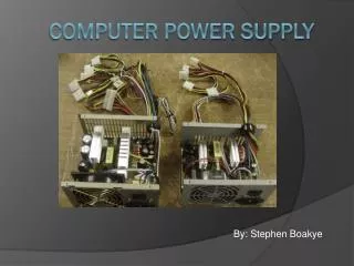
Computer Power Supply
Computer Power Supply. Amateur Radio Conversion For Cheap +12 vdc Power March 17, 2003. Advantages. Supplies are Readily Available They are Inexpensive ($1) 50 watt Radios Only Need 10-15 Amps New Supplies Have Higher Wattage 100 Watt HF Rig Potential Or Parallel Supplies. Requires.


Computer Power Supply
E N D
Presentation Transcript
Computer Power Supply Amateur Radio Conversion For Cheap +12 vdc Power March 17, 2003
Advantages • Supplies are Readily Available • They are Inexpensive ($1) • 50 watt Radios Only Need 10-15 Amps • New Supplies Have Higher Wattage • 100 Watt HF Rig Potential • Or Parallel Supplies
Requires • Some Electronic Knowledge • I = E/R P = E*I • Series/Parallel Resistance • Resistor Color Code • Volt Ohm Meter • Good vision!!! • Persistence • No Standard Design Concern For Safety
However! • With a Little Patience it’s a Lot of Fun • No Rocket Science Required • You Can Do as Much or as Little as You Feel Comfortable With • Quick and Dirty… (Just 12 vdc) • Moderate… (Try for 13.8 vdc) • Overhaul… (13.8 vdc only)
Scope of Presentation • Describe Quick and Dirty • Demonstrate 13.8 vdc Modification • Brief Description of In-depth Changes • Build Comfort Level
Assumptions • Power Supply Uses TL494 to Control Output • TL494 • Pin 2 is Reference Voltage • Pin 1 is Sample of Output Seems to be the “Norm”
Sample Regulation Circuit Reference Voltage From Supply Output
(1364.28 Ω) Lots of differences Voltage Regulation
KØGL Supply WØKRB Supply
TL 494 Blk = GND Red = +5 vdc Yellow = +12 vdc Blue = - 12 vdc White = - 5 vdc Voltage Adjust Pot KØGL Supply
Adjust Voltage TL494 WØKRB Supply
How To Start • Take Supply Apart • Blow Out Dirt • Verify Lead Colors (Red +5 vdc etc.) • Connect two 10 ohm 10 Watt Resistors in Parallel Across the +5 vdc Leads • Separate Wires and Power Up Supply • Measure Voltage and Check Fan
Measure Voltage & Check Fan Black Red Yellow Black 5 ohm Caution: Heat Sinks May be Electrically Hot! I = 5v/5Ω = 1A P = 5v x 1A = 5 watts
Once You Know It Works BE CAREFUL! • Find TL 494 • Trace Foil From TL494 Pin 1 • Measure Voltage on Pin 1 & 2 • Draw Schematic of Resistors • Compute Parallel/Series Resistance • Does Voltage on TL494 Pin 1 Make Sense • If so Decide How to Raise Voltage… • If Necessary…
Increase This Resistance NOTE Only +5 used for regulation Adjust Pot If Available Decrease Voltage On Pin 1 Or Decrease This One Voltage Regulation
Resistance Changes • It’s Easier to Lower Resistance Than to Increase It… • Just Put Another Resistance in Parallel • Lowering Resistance Between Pin 1 and Ground Will Decrease Voltage (Pin 1). • Regulation Will Immediately Adjust Voltage Back to Reference by Raising Output Voltage.
A Simple Spreadsheet Helps Determine Resistance Values for 13.5 volts R2 13.5 R1 C R2 WHAT IF? Note: After the presentation an additional slide was added to further explain this spreadsheet (Next page). Also if you double click the picture of the spreadsheet it will open Excel so you can look at the formulas. Finally the spreadsheet was changed so you can enter a different Reference voltage and all values will change accordingly. R2 WHAT IF? Yellow Indicates numbers that can be changed
Additional Notes on the Resistance Spreadsheet The TL 494 will try and maintain the reference voltage by raising the output voltage. This “constant” is used to find the current that must flow through R! at this voltage. C = 1.254/R1 • This spreadsheet was developed for a single power supply that had a reference voltage on Pin 2 on the TL494 of 1.254 volts. • With the spreadsheet changes you can now change the reference voltage in the cell in the bottom left. • The drawing at the left was the one that was used in the previous slide. • The first section only used R1 the second section used R1 and R1a in parallel. • The first part in each sections computes the current for R1 and gives the exact R2 that would be needed for 13.5 volts. • The WHAT IF part just gives you the chance to put a standard value in for R2 to see what the voltage output would be. • This was intended to just be a quick example of how a spreadsheet might help you compute resistance for one supply. Only in the parallel example.
Adjust Resistance for 13+ volts Temporary Wires Solder in Place Test Resistance
What to Expect? • Voltage on Pin 1 Will Stay the Same, Output Voltage Will Change. • You May Not Get to Exactly 13.8 Volts. • 13.5 Volts is Close Enough. • Check Voltage/Regulation Under Load. • Output Voltage Varies by Several Tenths
Note… • You Don’t Have to Solder Resistor to the Bottom of the Board • There Are Usually Two or Three Resistors in Parallel to Adjust Voltage. • Just Replace One or Two of Them This is How I Modified Ken’s Supply for 12 volt Regulation 12 v
What Next? • Mount 5 Ω Resistance Between Red and Black Lead (In Front of Fan if Possible) • Install Binding Posts • Use Several Yellow and Black Leads • AC Switch Installation Note:Ken’s Supply was Modified for 12 volt Regulation Only and the Supply Wouldn’t Output Until the 5 Ω Resistance was Added to the 5 volt Output
Watch What You Touch Just Because You can Increase the Voltage Doesn’t Mean You Have Regulation Make Sure You Know How to Power Up the Supply Getting the Cover Off of the Supply Can be a Challenge ¼ Watt Resistors are Hard to Read… If You Can Find the Resistors From Pin 1 to Ground You Can Just Put a Resistor in Parallel With Them Most of the Time Some Supplies Are Almost Too Full to Modify Lessons Learned
Overhaul Ideas… • Convert for +13.8 vdc Only • Change Regulation to Monitor +13.8 Volts • Move High Power Diodes from +5 volt Side to 12 volt Side of Supply • Add a Volt Meter • Move Fuse to Front Panel
Parallel Operation • I Put Two of the Supplies in Parallel and Tried My Old HT and the 60 Watt Amp • The Voltage Only Dropped .1 Volt Under Full Load • It Dropped Almost One Volt With Just One Supply Turned On • You Should Monitor Voltage During Use Note: With Only One Supply Turned On (In Parallel), Both Fans Run
The End Created by KØGL