Irradiator Specification
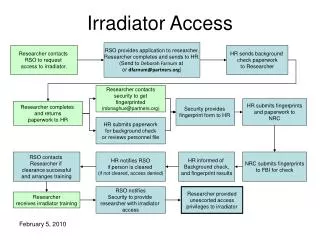
Irradiator Specification. Installation Qualification (IQ) + Software validation. Operational Qualification (OQ). Performance Qualification (PQ). Establish process for irradiation of product within predescribed limits. Characterize dose delivery of the

Irradiator Specification
E N D
Presentation Transcript
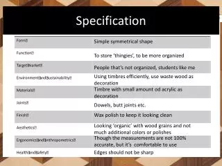
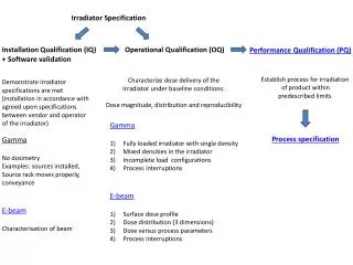
Irradiator Specification Installation Qualification (IQ) + Software validation Operational Qualification (OQ) Performance Qualification (PQ) Establish process for irradiation of product within predescribed limits Characterize dose delivery of the Irradiator under baseline conditions: Dose magnitude, distribution and reproducibility Demonstrate irradiator specifications are met (installation in accordance with agreed upon specifications between vendor and operator of the irradiator) • Gamma • Fully loaded irradiator with single density • Mixed densities in the irradiator • Incomplete load configurations • Process interruptions • E-beam • Surface dose profile • Dose distribution (3 dimensions) • Dose versus process parameters • Process interruptions Process specification Gamma No dosimetry Examples: sources installed, Source rack moves properly, conveyance E-beam Characterisation of beam
Installation Qualification of electron beam irradiator Characterisation of the electron beam • Position and shape of the beam spot (ensure product surface is covered) • Electron energy • Scan width and uniformity • Beam current Involve dosimetry Methods in ISO/ASTM 51649 Note: beam profile needs to be characterised at multiple distances from the conveyor
EXAMPLE: Beam width characterisation; Setpoint 60 cm 77 cm electrons 59 cm Distance from conveyor 32 cm Mark with pen at distance 25 cm (so peak not related to dose delivery)
EXAMPLE: Beam spot characterisation 77 cm electrons Distance from conveyor 32 cm Mark with pen (so peak not related to dose delivery)
EXAMPLE E-Beam energy measurement electrons Al Based on descending slope energy can be calculated (ASTM51649)
Operational Qualification of Gamma irradiator • “Standard operating conditions” i.e. Irradiator filled to design capacity with a • material of homogeneous density Dose distribution study • At least 2 different runs, each with a different density (“low” and “high”) • At least 3 irradiation containers in each run • 3-dimensional dosimeter grid DUR as function of density (compare with specification) Min and Max dose zone identified as function of density Dose magnitude study (scalability with timer setting) Variability of dose delivery Dose rate as function of density (throughput, compare with specification) 2) “At or beyond Standard operating conditions” of the irradiator Impact of density mixing on Dose magnitude and distribution Incompletely filled irradiation containers Process interruptions In the same run or even in the same irradiation container Compare results With those of 1)
Impact of density mixing on dose magnitude and distribution Transition Dose Map: • Low density (or empty) followed by high density loads • 1st and last dose map • Compare to homogeneous map Partial Load Map: • May use compensating dummy to center load product • Map at maximum dose locations and compare to fully loaded adjacent containers. Low density (or empty as worst case) followed by high density Dose map at least their interfase
Incompletely filled irradiation containers Partially filled irradiation container Dose map their interfase
Process interruption • Cycle source between fully up and fully down (multiple times) • Single material • Irradiation container adjacent to the source plane • Response of dosimeter might be influenced by fractionated • exposure
Operational Qualification of electron beam irradiator For all pathways (single – double sided exposure, different beam energy) • “Standard operating conditions” i.e. Irradiator filled to design capacity with a material of homogeneous density Surface dose map Demonstrate whole surface is effectively irradiated Dose distribution study • At least 1 run • At least 3 irradiation containers in each run • 3-dimensional dosimeter grid DUR (as function of density) Min and Max dose zone identified as function of density Dose magnitude study (scalability with process parameters) Variability of dose delivery 2) “At or beyond Standard operating conditions” of the irradiator Edge effects Product irradiated as a single entity Process interruption study All scenarios for interruption need to be included in the test program
EXAMPLE: Dose versus process parameters at an electron beam facility
EXAMPLE: Dose distribution in reference product (double sided exposure) 40cm high 0.15 g/cc stack of homogeneous material 10 MeV electron beam
EXAMPLE: Dose distribution in reference product (single sided exposure) 0.15 g/cc stack of homogeneous material 10 MeV electron beam
Process interruption study • Location closest to the scanhorn • 1-dimensional dosimeter strip in direction of product conveyance • Response of dosimeter might be influenced by fractionated exposure • Test all possible sources of interruptions e.g. Accelerator, conveyor, safety, electrical • Parameters at the extremes of operating conditions EXAMPLE: Accelerator interruption at maximum of conveyor speed
Performance Qualification, GOAL Determining dose delivery characteristics to product in a defined load configuration and for a specified process flow Acceptance criteria • Minimum and maximum dose zone determined • Variation of dose delivery characterized • Process capability for meeting specified dose range is assessed • Process monitoring practice established
Performance Qualification, METHOD Select a Product Load Configuration and a Process Flow • Product Dose Requirements • Irradiator Operational Qualification • Processing Efficiency Select a Performance Qualification dosimeter grid • Operational Qualification Dose Distribution Characteristics • Additional Locations to Account for Product Heterogeneity • Product Load Configuration / Orientation (partial fill of irradiation container) • Consider Routine Monitoring Practices Write protocol and get it approved by all parties Execute Analyse data Write report and get it approved by all parties
Process specification includes • Description of packaged product (dimensions, weight, orientation in shipper) and • acceptable variations • Loading pattern in the irradiation container • Conveyor path, process flow including lead / trail product if required • Setpoints and tolerances on irradiator parameters • Dose range of the product • Temperature restrictions • Restrictions on time between end of manufacturing and completion of irradiation • Process monitoring position, frequency and acceptance criteria • Any required re-orientation for multiple exposure
Questions: • Do you have a signed record on file stating all the characteristics of the irradiator? • Have you during IQ / OQ verified characteristics of the irradiator as they are mentioned • in that signed record with specifications? • Did PQ cover all scenarios of processing the product (partially filled cartons, • partially filled irradiation containers, ...) ? • Is the outcome of PQ detailed in a process specification? Is it sufficiently detailed • and signed by contract irradiator and product manufacturer?
References: • IAEA Guidelines for development, validation and routine control of industrial radiation • processes • ASTM 51649:2005 Practice for dosimetry in an electron beam facility for radiation • processing at energies between 300 keV and 25 MeV • ASTM 2303:2003 Standard guide for absorbed dose mapping in radiation processing • facilities • AAMI TIR 29:2012 Guide for process characterization and control in radiation sterilization • of medical devices • - ISO 11137 series