Download
1 / 34
340 likes | 360 Views
This article discusses the deep sea data transfer capabilities of KM3NeT, a next-generation deep water Cherenkov neutrino telescope. It explains how the data is transferred from the telescope to the shore using fiber optic telecommunications cables, and the importance of timing resolution in the detection process.

E N D
KM3NeT(http://www.km3net.org) Deep-sea data transfer at the KM3NeT neutrino telescope G. D. Hallewell Centre de Physique des Particules de Marseille For the KM3NeT Consortium
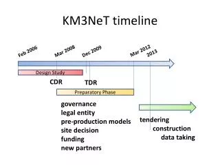
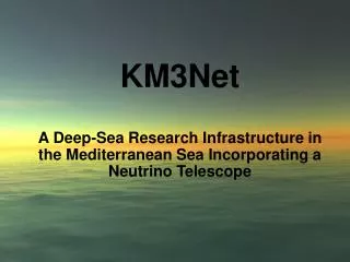
What is KM3NeT*? A Research Infractructure in the deep Mediterranean Sea - combining a next generation km3-scale deep water Cherenkov neutrino telescopewith a permanent infrastructure for deep-sea sciences: Oceanography, Marine Biology, Environmental Science, Geology & Geophysics • E.U. – funded 3-year design study (2/2006 12/2009) with 9M€ of European Union FP6 funding leading to a technical design report (TDR) end 2009 (CDR published in April 2008) • A ‘Preparatory Phase’ (2/2008 - 2011) funded through the European Union FP7 programme allowing collaboration & governance structures to be put in place, relations with industry established, development and characterisation of prototypes with a view to construction starting 2011 • *On the ESFRI* roadmap *European Strategy Forum on Research Infrastructures G. Hallewell , CPPM TWEPP09 Paris, September 21-25, 2009
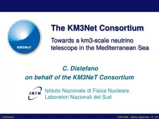
The KM3NeT Consortium 41 Institutes from 10 European Countries + participants from the three present-day Mediterranean n projects Cyprus: Univ. Cyprus Nicosia France: CEA/Saclay, CNRS/IN2P3 (APC Paris, CPP Marseille, IReS Strasbourg), Univ. Haute Alsace/GRPHE), IFREMER Germany: Univ. Erlangen, FTZ (Univ. Kiel), Univ. Tübingen Greece: HCMR Anavissos,HOU Patras, NCSR Athens, NOA/Nestor Athens, Univ. Athens Ireland: DIAS Dublin Italy: CNR/ISMAR,INFN (Univs. Bari, Bologna, Catania, Genova, Napoli, Pisa, Roma-1, LNS Catania, LNF Frascati), INGV, Tecnomare SpA Netherlands: NIKHEF/FOM Amsterdam, Univ. Amsterdam, Univ. Utrecht, KVI ( Univ. Groningen), NIOZ RomaniaISS Bucharest Spain: IFIC (CSIC) Valencia, Univ. Valencia, UP Valencia UK: Oceanlab (Univ. Aberdeen),Univ. Leeds, Univ. Liverpool, Univ. Sheffield Particle/Astroparticle institutes (33)–Sea science/technology institutes (8)–Coordination 3
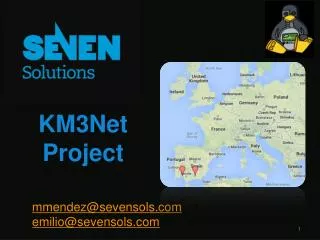
Possible sites for KM3Net in the MediterraneanSea 2500m 3800 – 5000m 3400m Ligurian W. Ionian E. Ionian
The KM3NeT Vision • Future cubic-kilometre scale neutrino telescope in the Mediterranean Sea • Exceeds Northern-hemisphere telescopes by factor ~50 in sensitivity (compared with ANTARES) • Exceeds IceCube sensitivity by substantial factor Angular resolution < 0.1° for muons with Em> 10 TeV • Focus of scientific interest: nastronomy @ 1-100 TeV Production mechanisms of high energy ns (acceleration mechanisms etc.) Investigation of the nature of astrophysical objects Origins of cosmic rays… • Indirect search for dark matter • Platform for deep-sea research (marine sciences) G. Hallewell , CPPM TWEPP09 Paris, September 21-25, 2009
Neutrino detection principle gč 43° m m (~ n) trajectory ANTARES detection principle 3D PMT array Importance of Timing Resolution For telescope point precision c in water ~ 20 cm/ns Chromatic dispersion ~ 1 ns / 20 m ~ ns timestamp precision, all hits, any storey m Typically 1g / PMT 40 m from m axis Čerenkov light from m nm 2500 - 5000 m depth Measurement : Time & position of hits m Measurement : Time & position of hits interaction n nm
Downward muon Signature Trigger hit Other hit + Used in fit
upward Muon signatures : general => Characteristic pattern in function of zenith angle and point of closest approach between line and track Downward (background)
Deep-sea data transfer at KM3NeT • Several hundred vertical detection lines, each of up to 120 optical modules (OMs) with PMTs, anchored to sea floor power & data transport network; • Data acquisition will minimize offshore electronics, reducing difficult and expensive maintenance operations. • ALL-DATA-TO-SHORE: - No off-shore triggering/filtering to combine signals from multiple OMs foreseen; all signals passing internal criteria (e.g. charge threshold) uploaded via fibreoptic telecommunications cable at overall worst case data rate of 100-400Gb/s using DWDM* colourmultplexing [* Dense Wavelength Division Multiplexing: up to 200 colours in 1550nm (C ) band] • Data transport and routing issues are discussed. G. Hallewell , CPPM TWEPP09 Paris, September 21-25, 2009
Music box or auto-piano principle… background rates on 10’’ PMTs canreach ~100 -200 kHz (bioluminescence) G. Hallewell , CPPM TWEPP09 Paris, September 21-25, 2009
Configuration Studies • Various geometries and OM configurations being studied; • None is optimal for all energies and directions; • “Local” (=on shore ~ 100 km away) coincidence requirement poses important constraints on OM grouping. G. Hallewell , CPPM TWEPP09 Paris, September 21-25, 2009
Optical Module Concepts Multi-PMT Optical Module: 31 * 3’’ PMs in 17’’ sphere • increased photocathode area • improved 1-vs-2 photo- electron separation • directionality Simplest concept: 8’’SBiAl - 10’’ BiAl PMT in 13-17’’pressure sphere ‘Capsule’ concept: 2 x 8’’ SBiAlPMTs Envelope: 2*10’’ hemispheresfused to cylinders. R&D with Schott; must withstand > 400 bar High QE bialkali p.c. (≥30%: anychosen tube) extendsCherenkov horizon
Data Rates for detection lines under worst case (40K + bioluminescence burst) conditions 8’’ - 10’’ PMT Multi-PMT OM: 31 * 3’’ PMTs 2 * 8’’ SBiAl PMTs Normal Idark + 40K decays (salt) (10” PMT)+ micro-organism bioluminescence @ -2500m (ANTARES) ~ 45 KHz Can peak @ 250 KHz levels (macro-organism passage) ; design for worse case. 91 detection line variant • Detection line of 20 storeys each 3 OMs , eq 250KHz; • 6 bytes TOT(48b) per SPE hit; • 720 Mb/s per full detection line; • 91 lines 65 Gb/s 127 detection line variant • Detection line of 20 storeys each 3 OMs , eq. 2*250KHz • ~10 -12 bytes TOT(80 -96b) per SPE hit; • ~3Gb/s per full detection line; • 127 lines 370 Gb/s Multi-PMT optical module variant (300 lines) • Detection line of 20 storeys, each 1 OM of 31* 3’’ PMTs; • 22.5 KHz noise per tube & 6 bytes (48 bits)/ SPE 1.1Mbps /tube • 670 Mb/s per full detection line; • 300 lines 200 Gb/s Such high levels (macro-organism spate) rare & seasonal (ANTARES)
A proposedreadoutschemewith shore based lasers and off-shore reflective electro absorption modulators (R-EAMS) Example: 100 coloursinterrogate modulators in 20 optical modules on each of 5 detectionlines Bidirectional: a circulator in eachdetection line PMT signal readout via time/multiple thresholds • Present data transmission rates reaching 40Gb/s per DWDM l in C (1550nm) band • 25 GHz colourchannelspacing (~ 0.25 nm) gives 200 chans; 50 GHz gives 100 ch • KM3NeT data rates conservative by these standards ~ < 25 Gb/s per fibre; 100 chans G. Hallewell , CPPM TWEPP09 Paris, September 21-25, 2009
‘Local’ coincidencesformed 100 km away; ‘TDCs’ canbeonshore, timing betweenarrivingedgesbut ASICsalsounderdevelopmentincorporating T.O.T. (see talk by L. Caponetto) G. Hallewell , CPPM TWEPP09 Paris, September 21-25, 2009
Proposedreadoutschemewith shore based lasers and off-shore reflective electro absorption modulators (R-EAMS) 10 Gb/s demonstration: one colourinterrogating Passive R-EAM @10 Gb/s through 100 km monomode fibre approximating KM3NeT configuration G. Hallewell , CPPM TWEPP09 Paris, September 21-25, 2009
Getting the data to shore: 50-100 km of deep sea fibre-optic telecommunications cable: Typical Deep Sea Telecommunications cable: 100 mm OD monomodefibres in stainless steel tube & armour vault, with only one(!) electrical conductor Mfrs: Alcatel-Lucent, Nexans, Tyco, NorddeutscheSeekabelwerke… Delivery by rail or cable ship loading at factory In Deep Water In shallow water
Use DWDM* in C band (1530 - 1565 nm)(Dense Wavelength Division Multiplexing)Presently up to 200 colours @ 25 GHz spacing Use Firewith a modern C. D. Specification (lowattenuation and dspersion) Chromatic dispersion cancomplicate life (signalscan arrive ~ 10 ns apart over 100 km, depending on l) Timing spreadsunder ITU-G.654 comparable with inter-storey time differences on muon trajectories ITU-G.655 compatibility (eg. Corning LEAF) preferred
Submarine detector line connection Detector line connestion Via ROV submarine manipulator: ANTARES d= 2500m (250 bar) Deep sea connections needed to heirarchy of Junction boxes and main site-to-shore cable
CONNECTOR SOCKET AND PLUG ANTARES has seenproblems with monomode (7um) core alignment in theseconnectors: New types anticipated…
Scalable Sea-Floor Cabling A Km3 detector means many detector units to be cabled. ANTARES experience teaches us that ROV wet-mateable connections (particularly fibreoptic) are a weak point. Reduce the numbers of wet-mateable connectors (also new types on the way) Interconnections in detection lines using ‘penetrators’ and fusion splices inside optical modules: Unipolar 10kV D.C. or A.C. (p.p.) delivered by site-top-shore cable: reduced to ~ 400V in primary and/or secondary junction boxes for seabed and vertical link distribution (see talk of M. Sedita) Various “Star” and “ring” data/power cabling layouts being considered
Hierarchical sea floor data/ power connection: possible schemes with varying levels of power and dataflow redundancy and scalability of construction G. Hallewell , CPPM TWEPP09 Paris, September 21-25, 2009
Standard Telecoms Universal Joint (UJ) Technology (penetrators) allows to build a scalable sea floor Junction box network without intermediate 10 kV HV connectors in the main trunk cables Branching Unit (HV, fibres) (Alcatel-Lucent, Greenwich, UK) Branching Unit (HV, fibres) (Alcatel -Lucent, Greenwich, UK) Junction box (Venus/Neptune oceanographic network, Canada) Penetrator entry
G. Hallewell , CPPM TWEPP09 Paris, September 21-25, 2009
G. Hallewell , CPPM TWEPP09 Paris, September 21-25, 2009
G. Hallewell , CPPM TWEPP09 Paris, September 21-25, 2009
Summary • KM3NeT will be one of the biggest (3) detectors ever built (V>1km3) hundreds of detection lines anchored in sea floor matrix, height up to 1km; • Connection to the coast up to 100 km distant: high bandwidth monomode fibreoptic transmission in standard telecoms cable; • Depth 2500 – 5000m (ambient pressures 250-500 bar) connectivity issues, minimum possible deployed electronics • Innovative optical module designs proposed; • Innovative readout scheme proposed with lasers on shore and modulators in optical modules: 1 colour /optical module or even/PMT well within current telecoms bandwidth capabilities ALL DATA TO SHORE: (UPGRADABLE) SHORE PROCESSING (EVEN LOW - LEVEL COINCIDENCE TRIGGERING) NOW CHEAPER THAN INACCESSIBLE SEA ELECTRONICS KM3NeT CDR published April 2008 (ISBN 978-90-6488-031-5), TDR now in preparation for publication - December 2009 G. Hallewell , CPPM TWEPP09 Paris, September 21-25, 2009
KM3NeT timeline Design Study Preparatory Phase Construction Jan 2008 Mar 2011 Feb 2006 Assembly model Tenders CDR TDR Financial plan Now Production model for detection unit
The KM3NeT Conceptual Design Report • Presented to the public at the VLVnT08 workshop in Toulon, April 2008 • Summarises (a.o.) • Physics case • Generic requirements • Pilot projects • Site studies • Technical implementation • Development plan • Project implementation available on www.km3net.org