Download
1 / 90
910 likes | 943 Views
Explore the use of mirrors in stereo vision systems for improved matching. Learn calibration parameters, rectification methods, and real-time depth map generation. Discover optimal rectifying transformations to minimize resampling effects.

E N D
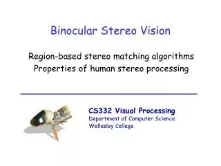
Vision Sensors for Stereo and Motion Joshua Gluckman Polytechnic University
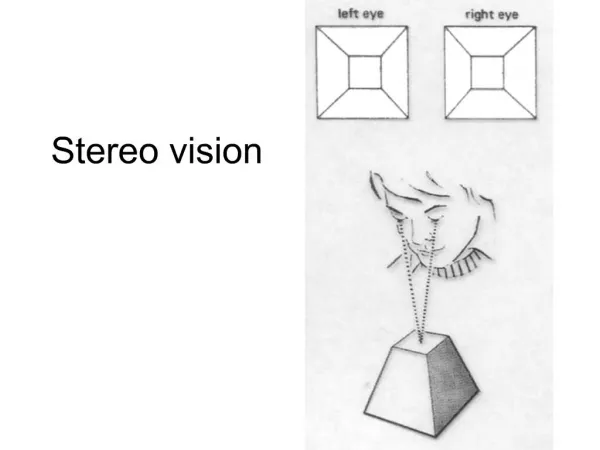
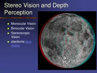
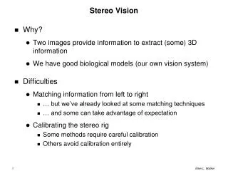
Stereo Vision depth map
Stereo With Mirrors [ Gluckman and Nayar (CVPR 99)]
Why Use Mirrors? • Identical system response • Better stereo matching • Faster stereo matching
Why Use Mirrors? • Identical system response • Better stereo matching • Faster stereo matching • Data acquisition • No synchronization • Data Storage
Stereo Systems Using Mirrors Mitsumoto `92 Inaba `93 Goshtasby and Gruver `93 Teoh and Zhang `84 Mathieu and Devernay `95 Zhang and Tsui `98
Background – Relative Orientation p p` C C` R,t – 6 parameters
Background – Epipolar Geometry p p` C e C` e`
Background – Epipolar Geometry 3 p p` C e C` e` 4 Epipolar geometry – 7 parameters
Background – Epipolar Geometry 3 p p` C e C` e` 4 Epipolar geometry – 7 parameters
One Mirror – Relative Orientation mirror virtual camera camera
One Mirror – Relative Orientation virtual camera camera 3 parameters
One Mirror – Relative Orientation virtual camera camera 3 parameters
One Mirror – Epipolar Geometry 2 parameters – location of epipole
Two Mirrors – Relative Orientation D virtual camera virtual camera camera
- 1 D 1 Two Mirrors – Relative Orientation - = = 1 D D D D D 1 2 1 2 virtual camera virtual camera D 2 camera
Two Mirrors – Relative Orientation virtual camera virtual camera q 5 parameters camera
4 Two Mirrors – Epipolar Geometry 6 parameters 2 p p` V e V` e`
image of the axis m Two Mirrors – Epipolar Geometry p` p epipole e` epipole e
image of the axis m Two Mirrors – Epipolar Geometry p1` p1 p2 p2` epipole e` epipole e p3` p3 p4 p4`
(b) (a) (c) (d)
Calibration Parameters Relative orientation Epipolar geometry
Get Images Rectify Matching Depth Map Real Time Stereo System Calibrate
Rectification of Stereo Images Perspective transformations
Why Rectify Stereo Images? • Fast stereo matching • O(hw2s) O(hw2) • Removes differences in rotation and scale
Rectification – Previous Methods Ayache and Hansen `88 3D methods – need calibration Faugeras `93 Robert et al. `93 2D methods – rectify from epipolar geometry Hartley `98 Loop and Zhang `99 Roy et al. `97 Non-perspective transformations Pollefeys et al. `99
The Bad Effects of Resampling the Images • Creation of new pixels causes • Blurs the texture • Additional computation • Loss of pixels • Loss of information • Aliasing [Gluckman and Nayar CVPR ’01]
Measuring the Effects of Resampling determinant of the Jacobian change in local area
Measuring the Effects of Resampling determinant of the Jacobian change in local area
Measuring the Effects of Resampling determinant of the Jacobian change in local area
Change In Aspect Ratio Preserves Local Area pixels created pixels lost
Skew Preserves Local Area aliasing
Minimizing the Effects of Resampling change in local area • P and P’ must be rectifying transformation • No change in aspect ratio and skew
e ¢ e e ¢ e The Class of Rectifying Transformations Fundamental matrix Rotation and translation
e ¢ e The Class of Rectifying Transformations
e ¢ e ¢ e e The Class of Rectifying Transformations
e ¢ e ¢ e e The Class of Rectifying Transformations 6 parameters
e ¢ e ¢ e e The Class of Rectifying Transformations no skew maintain aspect ratio 2 parameters
The Class of Rectifying Transformations scale perspective distortion 2 parameters
Finding the Best Rectifying Transform change in local area Find p1 and p8 that minimize e
Finding the Best Rectifying Transform change in local area Find p1 and p8 that minimize e • e is quadratic in p1 so the optimal scale can be found as a function of p8 • e is a 16th degree rational polynomial in p8
e e 1 2 Finding the Best Rectifying Transform • e1 and e2 are symmetric convex polynomials • e1 has a minimum at p8 = 0 • e2 has a minimum at p8 = f5 The minimum of e is between 0 and f5
e e 1 2 Finding the Best Rectifying Transform e1 and e2 depend on the location of epipoles epipoles at the same distance
e e 1 2 Finding the Best Rectifying Transform e1 and e2 depend on the location of epipoles epipoles at a distance of 3 and 10
Rectifying While Minimizing Resampling Effects Step 1: Rotate and translate the epipolar geometry