Download
1 / 38
380 likes | 399 Views
Explore the development and validation of a fuel vaporization model in the aviation industry, discussing theoretical flammability limits, simulant testing, and future research plans for enhanced safety measures.

E N D
Ongoing Fuel Flammability Work at the FAA Technical Center Steve Summer Project Engineer Federal Aviation Administration Fire Safety Branch, AAR-440 International Aircraft Systems Fire Protection Working Group London, UK June 13 – 14, 2002 IASFPWG – London, UK
Agenda • Fuel vaporization computer model – validation experiments • Theoretical flammability limits as a function of MIE, FP, and O2 content • Fuel vapor simulant for use in future ignition testing • Reports to be published IASFPWG – London, UK
Fuel Vaporization Model – Validation Experiments IASFPWG – London, UK
Acknowledgements • Professor C. E. Polymeropolous of Rutgers University • David Adkins of the Boeing Company IASFPWG – London, UK
Introduction • The original model proved a good method of predicting the evolution of hydrocarbons. • Results were presented by Prof. Polymeropolous (10/01 Fire Safety Conference) • Could prove to be a key tool in performing fleet flammability studies. • Fortran code has been converted to a user-friendly Excel spreadsheet by David Adkins of Boeing. IASFPWG – London, UK
Walls and Ceiling, Ts Liquid, Tl Physical Considerations • 3D natural convection heat and mass transfer within tank • Fuel vaporization from the tank floor which is completely covered with liquid • Vapor condensation/vaporization from the tank walls and ceiling • Multi-component vaporization and condensation • Initial conditions are for an equilibrium mixture at a given initial temperature Gas, Tg IASFPWG – London, UK
Major Assumptions • Well mixed gas and liquid phases within the tank • Uniform temperature and species concentrations in the gas and within the evaporating and condensing liquid • Rag≈109, Ral≈ 105-106 • Externally supplied uniform liquid and wall temperatures. Gas temperature is then computed from an energy balance • Condensate layer is thin and its temperature equals the wall temperature. IASFPWG – London, UK
Major Assumptions (cont’d) • Mass transport at the liquid–gas interfaces was estimated using heat transfer correlations and the analogy between heat and mass transfer for estimating film mass transfer coefficients • Low evaporating species concentrations • Liquid Jet A composition was based on previous published data and and adjusted to reflect equilibrium vapor data (Polymeropoulos, 2000) IASFPWG – London, UK
Assumed Jet A Composition • Based on data by Clewell, 1983, and adjusted to reflect for the presence of lower than C8 components IASFPWG – London, UK
Assumed Jet A Composition 25 20 MW: 164 15 % by Volume 10 5 0 5 6 7 8 9 10 11 12 13 14 15 16 Number of Carbon Atoms IASFPWG – London, UK
User Inputs • Equilibrium Temperature • Final Wall and Liquid Temperatures • Time Constants • Mass Loading • Tank Dimensions Note: For comparison with experimental results, recorded wall and liquid temperature profiles were entered directly in lieu of the final temperatures and corresponding time constants IASFPWG – London, UK
Program Outputs • Equilibrium gas & liquid concentrations/species fractionation • Species fractionation as a function of time • Ullage, wall and liquid temperatures as a function of time • Ullage gas concentrations as a function of time • FAR, ppm, ppmC3H8 IASFPWG – London, UK
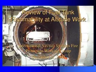
Experimental Setup • 17 ft3 vented tank placed inside environmental chamber. • Thermocouples used to monitor ambient, ullage, surface and fuel temperatures. • Blanket heater attached to bottom of tank used to heat fuel. • Hydrocarbon analyzer used to monitor ullage fuel vapors. IASFPWG – London, UK
Future Testing • Future tests to consist of: • Constant surface temperature tests. • Various steady state pressure (cruise) tests. • Varying pressure tests (flight profile). • Varying wall to wall temperature tests. • Varying fuel distribution tests. IASFPWG – London, UK
Future Model Improvements • Capability of varying tank pressure. • Capability of varying wall to wall temperature calculations. • Capability of varying fuel distribution. IASFPWG – London, UK
Theoretical Flammability Limits as a Function of MIE, FP & O2 Content IASFPWG – London, UK
Background • Present thinking in fuel tank inerting is that above x% O2, the tank is at risk throughout the entire flammability envelope, below x% O2 it is inert. IASFPWG – London, UK
Background • Previous work has shown how flammability limits vary as a function of ignition energy. IASFPWG – London, UK
Background • It follows intuitively that flammability limits will shift in a similar manner as inert gas is added to the fuel tank. • Thus, if your fuel tank is only partially inerted, the flammability exposure time has still been reduced by a significant amount. • How can this be quantified, validated and built into the flammability model? IASFPWG – London, UK
Computed Flammability Limits as a Function of O2 • Similar methodology as that in DOT/FAA/AR-98/26to compute flammability limits as a function of MIE. IASFPWG – London, UK
Computed Flammability Limits as a Function of O2 • Correlation of the variation of LOC with altitude. • Previously determined with a large (~20 J) spark source. IASFPWG – London, UK
Computed Flammability Limits as a Function of O2 • , where • Tmin is the minimum of the parabola given by Tmin = Tfp + 22 – 1.5Z. • a is a constant, determined by matching the curve as best as possible to the calculated 21% O2 curve for the given ignition energy. IASFPWG – London, UK
Resultant Curves for a 20 J Calculation IASFPWG – London, UK
Flammability Limits as a Function of MIE, O2 and FP • Combining this with the parabolic MIE calculations and LOC curves for various ignition energies, results in flammability limits which vary as a function of ignition energy, O2 concentration and flashpoint. • The sum of this work was put together into a working MS Excel model by Ivor Thomas, using the following LOC curves. IASFPWG – London, UK
Conclusions • By a set of simple calculations, one can obtain varying flammability limits as a function of ignition energy, O2 concentration and flashpoint. • Once validated, this data can be used in the flammability model to show reduction in fleetwide fuel tank flammability as a function of the amount of inert gas added to the tank. • Future tests to validate these calculations are planned at the technical center. IASFPWG – London, UK
Fuel Vapor Simulant for use in Future Ignition Testing IASFPWG – London, UK
Background • Our current method for ignition testing of Jet-A fuel vapors is extremely time consuming (up to as long as 2 hours per test). • If a gaseous mixture was available to simulate the flammability properties of Jet A, it would allow us to perform more tests quicker. IASFPWG – London, UK
Background • Availability of said mixture would also have applicability to other issues (e.g. explosion proof testing of pumps, etc.) • Subcommittee of SAE AE-5 currently being formed to look at this issue. IASFPWG – London, UK
Past Simulants - Hexane IASFPWG – London, UK
Past Simulants – Caltech Mixture • NTSB Docket No. SA-516, Exhibit No. 20O • Volumetric Ratio of H2:C3H8 of 5:1 • Examined the effect of fuel concentration, vessel size and ignition source on pressure history. IASFPWG – London, UK
Past Simulants – Caltech Mixture IASFPWG – London, UK
Proposed Research Activity at Tech Center • 20 L combustion vessel to be constructed within 4 – 6 weeks. • Variable energy (0.5 mJ – 5 J) spark source to be obtained within 8 – 10 weeks. • Tests to be conducted in a manner similar to the procedures layed out in ASTM flammability standards (e.g. E582, E2079, etc). IASFPWG – London, UK
Proposed Research Activity at Tech Center IASFPWG – London, UK
Reports to be Published IASFPWG – London, UK
Reports • Summer, S. M., Fuel Flammability Characteristics of JP-8 Fuel Vapors Existing Within a Typical Aircraft Fuel Tank, DOT/FAA/AR-01/54 • Summer, S. M., JP-8 Ignition Testing at Reduced Oxygen Concentrations, DOT/FAA/AR-xx/xx IASFPWG – London, UK