Download
1 / 40
430 likes | 509 Views
Learn network models like minimal-spanning tree, maximal-flow, and shortest-route techniques to solve various problems efficiently using software tools. Understand how to connect all points of a network while minimizing distance, determine maximum flow, and find the shortest path. Examples include connecting houses in a subdivision with minimal distance and maximizing traffic flow on road networks.

E N D
Chapter 12 Network Models Prepared by Lee Revere and John Large 12-1
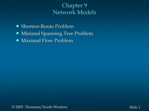
Learning Objectives Students will be able to: • Connect all points of a network while minimizing total distance using the minimal-spanning tree technique. • Determine the maximum flow through a network using the maximal-flow technique. • Find the shortest path through a network using the shortest-route technique. • Understand the important role of software in solving network problems. 12-2
Chapter Outline 12.1Introduction 12.2Minimal-Spanning Tree Technique 12.3Maximal-Flow Technique 12.4Shortest-Route Technique 12-3
Introduction • The presentation will cover three network models that can be used to solve a variety of problems: • the minimal-spanning tree technique, • the maximal-flow technique, and • the shortest-route technique. 12-4
Minimal-Spanning Tree Technique Definition: The minimal-spanning tree technique determines the path through the network that connects all the points while minimizing total distance. For example: If the points represent houses in a subdivision, the minimal spanning tree technique can be used to determine the best way to connect all of the houses to electrical power, water systems, etc. in a way that minimizes the total distance or length of power lines or water pipes. 12-5
The Maximum Flow Technique Definition: The maximal-flow technique finds the maximum flow of any quantity or substance through a network. For example: This technique can determine the maximum number of vehicles (cars, trucks, etc.) that can go through a network of roadsfrom one location to another. 12-6
Shortest Route Technique Definition: Shortest route technique can find the shortest path through a network. For example: This technique can find the shortest route from one city to another through a network of roads. 12-7
Minimal-Spanning TreeSteps • Selecting any node in the network. • Connecting this node to the nearest node minimizing the total distance. • Finding and connecting the nearest unconnected node. • If there is a tie for the nearest node, one can be selected arbitrarily. • A tie suggests that there may be more than one optimal solution. • Repeating the third step until all nodes are connected. 12-8
Minimal-Spanning Tree Technique Solving the network for Melvin Lauderdale construction • Start by arbitrarily selecting node 1. • Since the nearest node is the third node at a distance of 2 (200 feet), connect node 1 to node 3. • Shown in Figure 12.2 (2 slides hence) • Considering nodes 1 and 3, look for the next-nearest node. • This is node 4, which is the closest to node 3 with a distance of 2 (200 feet). • Once again, connect these nodes (Figure 12.3a (3 slides hence). 12-9
Summarize: Minimal-Spanning Tree Technique Step 1:Select node 1 Step 2:Connect node 1 to node 3 Step 3:Connect the next nearest node Step 4:Repeat the process • The total number of iterations to solve this example is 7. • This final solution is shown in the following slide. 12-14
Final Solution to the Minimal-Spanning Tree Example • Nodes 1, 2, 4, and 6 are all connected to node 3. Node 2 is connected to node 5. • Node 6 is connected to node 8, and node 8 is connected to node 7. • All of the nodes are now connected. • The total distance is found by adding the distances for the arcs used in the spanning tree. • In this example, the distance is: 2 + 2 + 3 + 3 + 3 + 1 + 2 = 16 (or 1,600 feet). 12-16
Maximal-Flow Technique • The maximal-flow techniqueallows the maximum amount of a material that can flow through a network to be determined. • For example: • It has been used to find the maximum number of automobiles that can flow through a state highway system. • An example: • Waukesha is in the process of developing a road system for downtown. • City planners would like to determine the maximum number of cars that can flow through the town from west to east. • The road network is shown in Figure 12.6 (next slide). 12-17
Road Network forWaukesha • Traffic can flow in both directions. 12-18
Maximal-Flow Technique (continued) The Four Maximal-Flow Technique Steps: • Pick any path from the start (source) to the finish (sink) with some flow. • If no path with flow exists, then the optimal solution has been found. • Find the arc on this path with the smallest flow capacity available. • Call this capacity C. • This represents the maximum additional capacity that can be allocated to this route. • For each node on this path, decrease the flow capacity in the direction of flow by the amount C. • For each node on this path, increase the flow capacity in the reverse direction by the amount C. • Repeat these steps until an increase in flow is no longer possible. 12-19
Solving the WaukeshaExample • Start by arbitrarily picking the path 1–2–6, at the top of the network. • What is the maximum flow from west to east? It is 2 because only 2 units (200 cars) can flow from node 2 to node 6. • Now we adjust the flow capacities (Figure 12.7). As you can see, we subtracted the maximum flow of 2 along the path 1–2–6 in the direction of the flow (west to east) and added 2 to the path in the direction against the flow (east to west). • The result is the new path in Figure 12.7 (next slide). 12-20
Iteration 1 Add 2 2 1 2 2 East Point Subtract 2 6 3 West Point 1 0 3 2 4 East Point 6 1 New path West Point 1 Capacity Adjustment 12-21
Solving the WaukeshaExample 0 3 2 4 East Point 6 1 New path West Point 1 • The New Path reflects the new relative capacity at this stage. • The flow number by any node represents two factors. • One factor is the flow that can come fromthat node. • The second factor is flow that can be reducedcoming intothe node. • The number 1 by node 1 indicates that 100 cars can flow from node 1 to node 2. 12-22
Solving the WaukeshaExample 0 3 2 4 East Point 6 1 New path West Point 1 • The number 0 by node 2 on the path from node 2 to node 6 indicates that 0 cars can flow from node 2 to node 6. • The number 4 by node 6, on the path from node 6 to node 2, indicates that we can reduce the flow into node 6 by 2 (or 200 cars) and that there is a capacity of 2 (or 200 cars) that can come from node 6. • These two factors total 4. 12-23
Solving the Waukesha Example 0 3 2 4 East Point 6 1 New path West Point 1 • On the path from node 2 to node 1, the number 3 by node 2 shows that we can reduce the flow into node 2 by 2 (or 200 cars) and that there is a capacity of 1 (or 100 cars) from node 2 to node 1 • At this stage, there is a flow of 200 cars through the network from node 1 to node 2 to node 6. • The new relative capacity reflects this. 12-24
Repeat the Process • Now, repeat the process by picking another path with existing capacity. • Can arbitrarily pick path 1–2–4–6. • The maximum capacity along this path is 1. • In fact, the capacity at every node along this path (1–2–4–6) going from west to east is 1. • Remember, the capacity of branch 1–2 is now 1 because 2 units (200 cars per hour) are now flowing through the network. • So, need to increase the flow along path 1–2–4–6 by 1 and adjust the capacity flow (see next slide). 12-25
Fig-12.8a: Second Iteration for Waukesha Add 1 2 6 1 4 1 1 1 1 1 Subtract 1 3 Old Path 12-26
Fig-12.8b: Second Iteration for Waukesha 0 4 2 0 4 East Point 6 2 0 0 West Point 2 2 0 1 0 4 10 1 6 5 0 3 1 3 2 New Network 12-27
Continuing the Process • Now, there is a flow of 3 units (300 cars): • 200 cars per hour along path 1–2–6 plus • 100 cars per hour along path 1–2–4–6 • Can the flow be further increased? • Yes, along path 1–3–5–6. • This is the bottom path. • The maximum flow is 2 because this is the maximum from node 3 to node 5. • The increased flow along this path is shown in the next slide. 12-28
0 4 2 0 4 East Point 6 2 0 0 West Point 2 2 0 1 0 4 10 1 Subtract 2 6 5 0 3 1 3 2 Add 2 Third Iteration 12-29
Continuing the Process Again, repeat the process. • Try to find a path with any unused capacity through the network. • Carefully checking the third iteration in the last slide reveals that there are no more paths from node 1 to node 6 with unused capacity, • even though several other branches in the network do have unused capacity. • The final network appears on the next slide. 12-30
0 4 2 0 4 East Point 6 2 0 2 West Point 2 2 0 1 0 4 10 1 4 5 0 3 3 3 0 Final Iteration New Path Path = 1, 3, 5, 6 12-31
Final Network Flow (Cars per Hour) PATHFLOW 1-2-6 200 1-2-4-6 100 1-3-5-6 200 Total =500 The maximum flow of 500 cars per hour is summarized in the following table: 12-32
The Shortest-Route Technique • The shortest-route technique minimizes the distance through a network. • The shortest-route technique finds how a person or item can travel from one location to another while minimizing the total distance traveled. • The shortest-route technique finds the shortest route to a series of destinations. 12-33
Example: From Ray’s Plant to Warehouse For example, • Every day, Ray Design, Inc., must transport beds, chairs, and other furniture items from the factory to the warehouse. • This involves going through several cities. • Ray would like to find the route with the shortest distance. • The road network is shown on the next slide. 12-34
200 Plant 4 2 100 100 100 150 6 1 50 100 200 5 3 40 Warehouse Shortest-Route Technique (continued) Roads from Ray’s Plant to Warehouse: 12-35
Steps of the Shortest-Route Technique • Find the nearest node to the origin (plant). Put the distance in a box by the node. • Find the next-nearest node to the origin (plant), and put the distance in a box by the node. In some cases, several paths will have to be checked to find the nearest node. • Repeat this process until you have gone through the entire network. The last distance at the ending node will be the distance of the shortest route. 12-36
Shortest-Route Technique (continued) 200 Plant 4 2 100 100 100 150 6 1 50 100 200 5 3 40 Warehouse Ray Design: 1st Iteration 100 • The nearest node to the plant is node 2, with a distance of 100 miles. • Thus, connect these two nodes. 12-37
Shortest Route Technique (continued) 100 200 100 100 4 2 100 150 50 100 200 6 1 40 150 5 3 Ray Design: 2nd Iteration • The nearest node to the plant is node 3, with a distance of 50 miles. • Thus, connect these two nodes. 12-38
Shortest-Route Technique (continued) 100 200 100 100 4 2 100 150 50 100 200 6 1 40 190 150 5 3 Ray Design: 3rd Iteration • The nearest node to the plant is node 5, with a distance of 40 miles. • Thus, connect these two nodes. 12-39
Shortest Route Technique (continued) 100 200 100 100 4 2 100 150 50 100 200 6 1 40 190 150 5 3 4th and Final Iteration 290 Total Shortest Route = 100 + 50 + 40 + 100 = 290 miles. 12-40