Chapter 2 Network Models
Chapter 2 Network Models. 2-1 LAYERED TASKS. There are 3 different activities at the sender site and 3 at the receiver site. Must be done in the order of the layers. Each layer at the sending site uses the services of the layer right below it.

Chapter 2 Network Models
E N D
Presentation Transcript
Chapter 2 Network Models
2-1 LAYERED TASKS • There are 3 different activities at the sender site and 3 at the receiver site. • Must be done in the order of the layers. • Each layer at the sending site uses the services of the layer right below it. Figure 2.1 Tasks involved in sending a letter
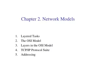
2-2 THE OSI MODEL • Established in 1947, the International Standards Organization (ISO) is a multinational body dedicated to worldwide agreement on international standards. • An ISO standard that covers all aspects of network communications is the Open Systems Interconnection (OSI) model. It was first introduced in the late 1970s. • ISO is the organization. OSI is the model. • Topics covered: • Layered Architecture • Peer-to-Peer Processes • Encapsulation
2-2 THE OSI MODEL • Why use a layered approach ? • Data communications requires complex procedures • Sender identifies data path/receiver • Systems negotiate preparedness • Applications negotiate preparedness • Translation of file formats • For all tasks to occur, a high level of cooperation is required • Provide framework to implement multiple specific protocols per layer
2-2 THE OSI MODEL • Advantages of Layering • Easier application development • Network can change without all programs being modified • Breaks complex tasks into subtasks • Each layer handles a specific subset of tasks • Communication occurs • between different layers on the same node or stack (INTERFACES) – vertical communications • between similar layers on different nodes or stacks (PEER-TO-PEER PROCESSES) – horizontal communications
Figure 2.3 The interaction between layers in the OSI model User support layers Network support layers
2-3 LAYERS IN THE OSI MODEL Figure 2.5 Physical layer The physical layer is responsible for movements of individual bits from one hop (node) to the next. • The interface and the type of the physical transmission medium • Raw bits -> signals • Bit duration • How the devices are connected to the media (point-to-point, or multipoint) • How devices are connected to each other(mesh, star, ring, bus, or hybrid) • The direction of transmission( simplex, half-duplex, or full-duplex).
Figure 2.6 Data link layer The data link layer is responsible for moving frames from one hop (node) to the next. • Makes the raw transmission facility (physical layer), reliable. Error-free to the upper layer (network). • Divides the stream of bits into frames (data units) • Adds a header to define the send and/or receiver of the frame • Flow control mechanism to avoid overwhelming the receiver (receiver slower than sender). Detect and retransmit damaged or lost frames. Recognize duplicate frames.
Figure 2.7 Hop-to-hop delivery • Communication at the data link layer occurs between two adjacent nodes. • For a to f, 3 partial deliveries are made. a to b, b to e, and e to f. Different headers.
Figure 2.8 Network layer The network layer is responsible for the delivery of individual packets from the source host to the destination host. • Ensures that each packet gets from origin to final destination. • If two systems are connected to the same link, there is usually no need for a network layer. If different links, need. • Network layer adds logical addresses of the sender and receiver • Routing: routers/switchers route or switch the packets to their final destination.
Figure 2.9 Source-to-destination delivery When packet gets B, B makes a decision based on the final F. B is a router, it uses its routing table to find that the next hop is router E, so send to E.
Figure 2.10 Transport layer The transport layer is responsible for the delivery of a entire message from one process to another. • Ensures the whole message arrives intact and in order, overseeing both error control and flow control at the source-to-destination level. • Service-point addressing: specific process (like email, msn, etc) • A message is divided into segments, containing a sequence number
Figure 2.11 Reliable process-to-process delivery of a message
Figure 2.12 Session layer • Establishes, maintains, and synchronized the interaction among communicating systems. • Synchronization: allows a process to add checkpoints, or synchronization points, to a stream of data. • •Responsible for enforcing the rules of dialog (e.g., Does a connection permit half-duplex or full-duplex communication?), synchronizing the flow of data, and reestablishing a connection in the event a failure occurs.
Figure 2.13 Presentation layer The presentation layer is responsible for translation, compression, and encryption. • Provides for data formats, translations, and code conversions. • Concerned with syntax and semantics of data being transmitted. • Encodes messages in a format that is suitable for electronic transmission. • Data compression and encryption done at this layer. • Receives message from application layer, formats it, and passes it to the session layer.
Figure 2.14 Application layer The application layer is responsible for providing services to the user.
2-4 TCP/IP PROTOCOL SUITE • The layers in the TCP/IP protocol suite do not exactly match those in the OSI model. The original TCP/IP protocol suite was defined as having four layers: host-to-network, internet, transport, and application. • However, when TCP/IP is compared to OSI, we can say that the TCP/IP protocol suite is made of five layers: physical, data link, network, transport, and application. • Topics covered: • Physical and Data Link Layers • Network Layer • Transport Layer • Application Layer
2-5 ADDRESSING Four levels of addresses are used in an internet employing the TCP/IP protocols: physical, logical, port, and specific. Figure 2.17 Addresses in TCP/IP
Figure 2.19 Physical addresses • A node with physical address 10 sends a frame to a node with physical address 87. The two nodes are connected by a link (bus topology LAN). • The computer with physical address 10 is the sender, and the computer with physical address 87 is the receiver. • In most data link protocols, the destination address (87) comes before the source address (10).
Most local-area networks use a 48-bit (6-byte) physical address written as 12 hexadecimal digits; every byte (2 hexadecimal digits) is separated by a colon. 07:01:02:01:2C:4B A 6-byte (12 hexadecimal digits) physical address.