Download
1 / 33
330 likes | 379 Views
Explore the transmission network in South Korea, focusing on the newly commissioned 765kV system. Learn about infrastructure, statistics, facilities, and upgrades in the country's power supply.

E N D
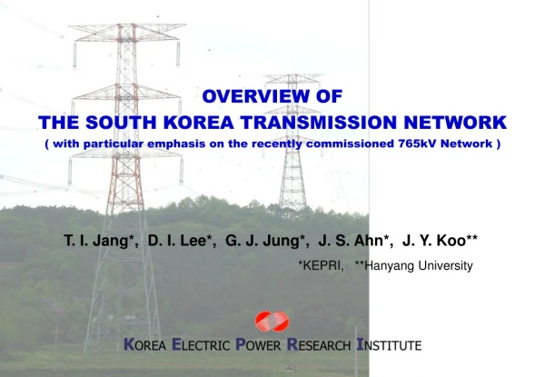
OVERVIEW OFTHE SOUTH KOREA TRANSMISSION NETWORK( with particular emphasis on the recently commissioned 765kV Network ) KOREAELECTRICPOWERRESEARCHINSTITUTE T. I. Jang*, D. I. Lee*, G. J. Jung*, J. S. Ahn*, J. Y. Koo** *KEPRI, **Hanyang University
345 & 765kV Transmission Lines of Korea 1st Project 2nd Project 3rd Project 345kV T/L
AGENDA Overview of Korea Power Statistics • Load • Generation • Transmission Lines • Substation Introduction of Korea 765 kV System • Transmission Lines • Substation
Load Trends of Korea Energy Sales [GWh] Peak Load [MW] Comsumption per capita [kMh]
Trend of Generating Facility Total : 53,801 [MW] (2002) Thermal : 63.6% Nuclear : 29.2% Hydro : 7.2%
Trend of Transmission Line Length Total : 27,937 [c-km] (2002) 154kV : 65.0% 345kV : 26.8% Below 66kV : 5.0% 765kV : 2.4% DC 180kV : 0.8%
Trend of Capacity of Transformer Total : 160,838 [MVA] (2002) 154kV : 51.9% 345kV : 42.9% 765kV : 4.4% Below 66kV : 0.8%
Overview of 765kV Facilities Transmission Lines: 330 km (1st Project) • Conductor : ACSR 480 mm2 6 Bundles • Ground Wire : AW 200 mm2, OPGW 200 mm2 • Switching Surge : 1.9 p.u. & TOV : 1.2 p.u. • Tower Foundation : pad & chimney, pier etc. • Tower Design • - Type: Pipe - Span: 500~600 m • - Height: 80~100 m - Weight: 70~100 tons • Insulator String : 300 kN, 400 kN, 530 kN Substation: 4 substations (1st Project) • Type: outdoor GIS • BUS Scheme: 2 BUS 1.5 CB • 765 kV 8 T/L, 4 Transformer Bank (or 5 Bank) • Site Area: approximately 235,000 m2 • Transformer: 1 Ph, 666 MVA 3 (765/345/23 kV) • - BIL: 2,050 kV - Weight: 150 tons • Circuit Breaker: rated current 8 kA • - BIL: 2,250 kV - Short Circuit Cap.: 50 kA
Characteristics of Korea 765kV Upgrading 4.7 times of 345kV 1,800,000kW 8,400,000kW Necessities • Increasing Rate of Peak Demand : average 10 % / year • Difficulty of Obtaining on Rights-of-way Upgrading Advantage (765kV : 345kV) • Increasing of Transmission Capacity 345 kV 765 kV
Decreasing of Transmission Loss : 20 % of 345 kV • Decreasing of Tower Area : 50% • Decreasing of Transmission Line Route Area : 30 % 53% of 345kV
Conductor Cross sectional view of wires 6 bundle conductor and spacer
Ground Wire & Jumper of Tension Tower Ground Wire AW 200mm2 and OPGW 200mm2 Jumper Suspension rod type pre-fab Jumper
Kinds of Insulator String • Suspension String : 300 kN 2, 400 kN 2 • V Suspension String for Jumper : 210 kN 2 • Tension String : 400 kN 3 Impulse test of suspension insulator Arc-resistivity test of arcing horn
Typical 765 kV Transmission Tower Suspension Type Tension Type
Tower Design • Kind of members : pipe (arm part is angle) • Tower Type • - Type: A, LA, B, C, D, D0, X (dead end tower) • - C type and above (heavy angle tower): asymmetric arm • - Inside arm is shorter than the outside arm • Accessories : Ladder, Rail for Lift, Resting places etc. Manufacturing of 765 kV tubular tower Lift for tower and its rail
Foundation Design Ordinary foundation • pier & pad foundation, pier foundation, rock anchor foundation Special foundation • pile foundation, well foundation Pier foundation Excavation of pier foundation using Telescopic Setting the stub
Design of Ground Clearance • Electric Field on ground level = 3.5 kV/m (resident area) • 7.0 kV/m (mountain area)
Electrical Environment Design Test Results from long term tests for 28 months Cardinal Conductor (480mm2 x 6 Bundle / Phase) satisfies the KEPCO design Criteria
Insulation Design Overvoltage Analysis Results • Power Frequency Temporary Overvoltageis below 1.2 p.u. • - 1.2 p.u. (analysis results) + margin = 1.2 p.u. • Line-to-Ground Fault Initiationis below 1.8 p.u. • - No Reduction Method • Energization & Re-energizationwith one step per-insertion resistor is below 1.9 p.u. • - Maximum Resistor Value 800 Ohms (Optimum = 400 Ohms) • Simultaneous Single Line-to-Ground Fault Clearing at each circuit is below 1.9 p.u. • - Without Opening Resistor
Lighting Flashover Rate Shielding Angle • Calculated Condition • - IKL : 20 • - Shielding Angle : -8 degree • - Hill Side Angle : 10 degree (average) • - Tower Foot Resistance : 15 ohms • - Horn Gap Length : 4.6 m, 4.8 m (765 kV) • 2.34 m (345 kV) Ground wire arm is longer than lower arm by 1 m and shielding angle of upper conductor is approximately –8 degrees.
Type of substation Type : Outdoor Full GIS Type • With no exposure of hot-line parts, except for the bushing at the front • end of incoming T/L • Most equipment is installed inside a metal enclosure which is • insulated with SF6 gas • GIS and Transformer are connected with a SF6 Gas Insulated Bus • (GIB) BUS Scheme : Double Bus 1.5CBs Type • Highly reliable (in case of bus failure), flexible (in power flows) and • economical • Enough operational experience with this type: • - The standard bus scheme in the 345 kV S/S
View of 765 kV Substation 765kV Sin Ansung S/S
Insulation Design Basic Concept • External over voltage: Suitable arrangement of high performance surge arrester • Internal over voltage: No flash over Internal over voltage criteria Standard Insulation Distance
Main Power Transformer • 2 tanks for each phase: possibility of transportation • It is possible to operate 1 tank for each phase
MTr. DAS Optical LAN Client Server Printer Server GIS DAS CCU HUB To Control system Preventive Diagnostic System • On-line diagnosis of the operating status of apparatuses • Use accumulated data to prepare an optimal maintenance and • repair plan according to the condition of devices 765 kV Predictive diagnostic system configuration
Environmental Countermeasures • Full GIS type • Colored water-permeable concrete at the switch yard surface • A barrier of trees on the outside • Application of 3D graphic simulation Bird’s eye view 3D graphic simulation
Conclusions 765kV Transmission Line of Korea is the first 765kV double circuit AC T/L in the world Characteristics of 765kV Transmission Lines • Bulk Carrying Capacity ( 8,400 MW ): 5 times of 345 kV • Efficient Utilization for Land ( 529 m2): 53% of 345 kV • Cost Reduction in Construction ( 3,900 million Won/km ): 74% of 345 kV per kW • Decrease in Transmission Loss ( 0.05% ): 20% of 345 kV • Environment Affinity 765 kV Transmission Line: EMF, Corona Exporting of Technology • Vietnam, Myanmar, Libya, China, etc.