Download
1 / 13
130 likes | 175 Views
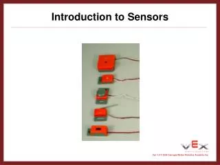
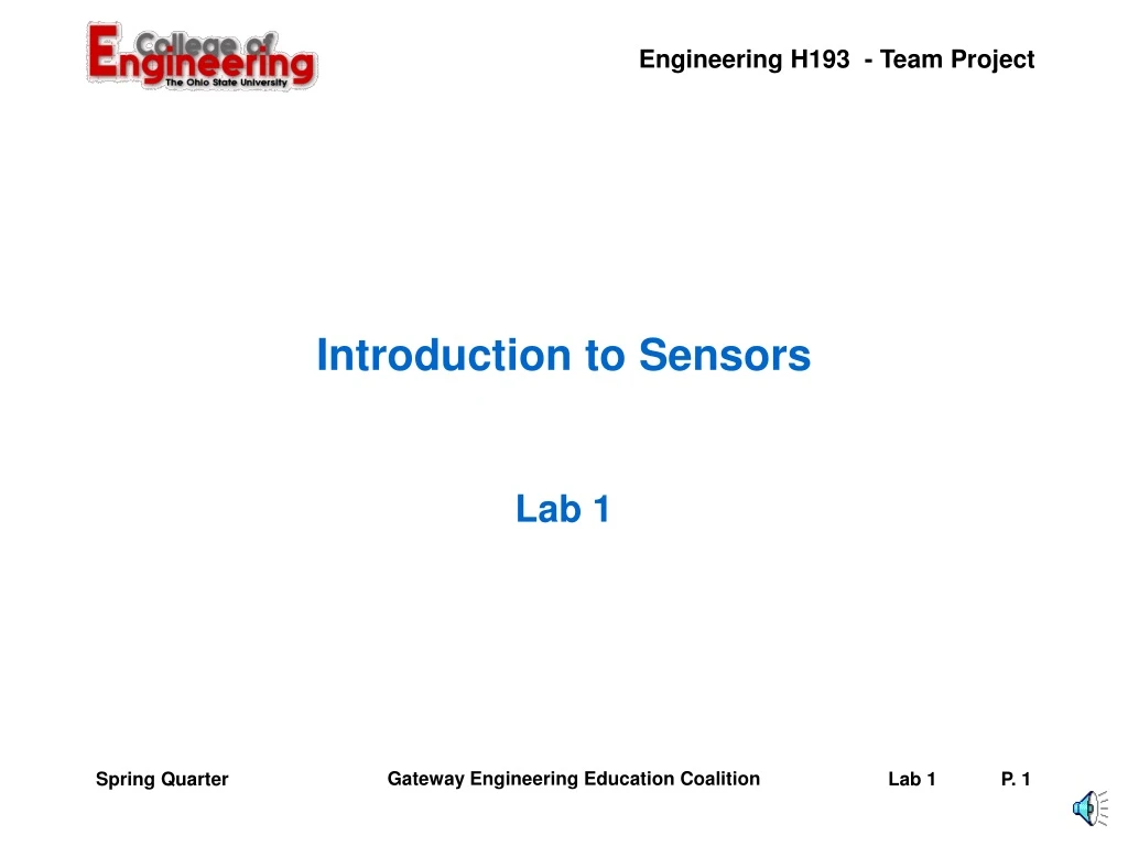
Introduction to Sensors. Lab 1. Today’s Laboratory. Purpose: The purpose of this lab is to expose your team to some of the sensors that you might use in your robot design. Learn the basic operating principles of micro-switches and photo sensors (CdS cells).

E N D
Introduction to Sensors Lab 1 Spring Quarter
Today’s Laboratory • Purpose: • The purpose of this lab is to expose your team to some of the sensors that you might use in your robot design. • Learn the basic operating principles of micro-switches and photo sensors (CdS cells). • Write and run a program to control the speed and direction of an erector set motor using a microswitch and a CdS cell. • Learn how to test the motor ports, analog ports, and digital ports of your handyboard. Spring Quarter
Procedure • Connect the Handyboard to the computer using the interface board, phone cable, and serial cable provided. • Run Interactive C on your computer. Follow the instructions to download pcode to your handy board. Select the file Handy_Board_1.2.icd when prompted. Spring Quarter
Procedure • Determine if your Handyboard is working correctly by loading and running the program "hbtest.c". This program will allow you to check the motor ports, analog ports, digital ports, and the control knob. Run the following subroutines (one at a time) by typing them at the bottom of the Interaction Window. • testmotors(); • testdigitals(); • testanalogs(); Spring Quarter
Gearhead Motor • Trim a male header strip (use three pins only) and solder it to the wire leads of the gearhead motor (See Section 6 of the Handyboard technical reference.) • Connect the motor to one of the motor ports. Spring Quarter
Gearhead Motor • Write a program using the motor(int m, int p) command to turn the motor on and off, and to reverse its direction. • Do not exceed a power level of 60~65 (instead of 100). This is to avoid burning the motor (which is rated at 6 V). • Use printf statements to show the status of the motor on the LCD screen. Spring Quarter
Solder a microswitch to a two-wire ribbon cable. Trim a male header strip (use four pins only) and solder it to the other end of the ribbon cable (See figures on section 6 of the handyboard technical reference. ) Microswitch Spring Quarter
Microswitch • Connect the microswitch to a digital port. • Write a program that allows the motor to run while the microswitch is "not pressed" (switch open). The motor should stop whenever the microswitch is "pressed" (switch closed). Use printf statements to show the status of both the motor and the microswitch on the LCD screen. Spring Quarter
CdS (Cadmium Sulfide) Cell • Plug a CdS cell directly to an analog port of the handyboard. • Write a command to print the output of the CdS cell on the LCD screen. Spring Quarter
System to Sense and Control • Connect the erector set motor, the microswitch, and the CdS cell to the Handyboard • Write a program that will continuously change the speed and direction of the motor based on the output of the CdS cell. • Use the start button on the Handyboard to run the motor at a maximum power level of 60~65 in one direction. • As you cover the CdS cell with your hand, the motor will slow down, stop, reverse its direction of rotation, and run at a power level of 60~65. • The motor should stop whenever the microswitch is pressed (switch closed) or when the stop button is pressed. Spring Quarter
System to Sense and Control • NOTE: Make sure that each team member can operate the Handyboard including setup, initialization, connection of devices, operating the devices in command mode, writing code in IC, and operating the devices under program control. Spring Quarter
Individual lab reports • Four pages maximum (including cover page, sketches, and attachments). • Cover page: title, name, section, team #, date, and professor. • Description of the lab procedure, problems encountered, and how problems were solved. • Include a sketch of the controller, motor, microswitch, and CdS cell connected. Use labels to indicate the ports used. • Include copies of the programs used for parts 5 and 6. Spring Quarter
Questions ? Spring Quarter