Solar Orbiter EUV Spectrometer Thermal Design Considerations
140 likes | 228 Views
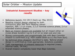
This technical document discusses the thermal design considerations for the EUV Spectrometer onboard the Solar Orbiter spacecraft. Topics covered include heat rejection, radiator capabilities, design options, heat pipes, thermal modeling, and detector cooling strategies.

Solar Orbiter EUV Spectrometer Thermal Design Considerations
E N D
Presentation Transcript
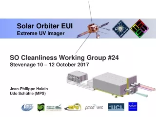
Solar Orbiter EUV Spectrometer Thermal Design Considerations Bryan Shaughnessy
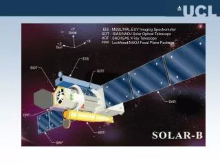
Spacecraft Sunshield Aperture (100mm*100mm) Primary Mirror (100mm*100mm) Baffles Optical path Width = 0.3m Length 1.4 m Slit Assembly Grating Heat Stop Basic Configuration Detector Assembly
Basic Thermal Requirements • Detector temperature < -60 deg C (target -80 deg C) • Structure and optics: • Multilayer coatings (if used) are assumed to be a limiting factor. < 100 deg C assumed at present. • Thermal Control System Mass TBD • Thermal Control System Power TBD (minimise)
Cold case non operational Hot case non operational Start Up Cold Case Operational Hot Case operational Thermal Environment
103 W Absorbed at baffles 100 W 250 W 200 W Absorbed at primary 50 W 3 W 47 W Absorbed at heat stop (‘focussed’) Solar Thermal Loads at 0.2 AU 350 W Through Aperture (Absorbing Optics/No Aperture Filter)
Irradiance Profile at Primary Mirror(No Aperture Filter) 20 KW/m2 15 KW/m2 25 KW/m2 30 KW/m2 35 KW/m2
The Thermal Challenges • Reject heat input to system of ~350W at 0.2AU • Filter at aperture? • Maintaining sensible temperatures/gradients within instrument • Getting heat to radiators (or to spacecraft cooling system) • Spreading the heat across the radiators • Prevent heat loss when instrument is further from the Sun • Maintaining sensible temperatures within instrument • Minimising heat transfer to radiators (or to spacecraft cooling system) • Minimising power required for survival heaters
Heat Rejection by Radiators • Radiator heat rejection capability a function of: • Emissivity ~ 0.95 for black paint • Efficiency ~ 0.96 • View-factor to space ~ 0.95 • How to transfer heat to radiator?
Thermal Design Options • Solar absorptivity of the optics: • High (i.e., SiC) – remove more heat from primary mirror • Low (e.g., gold coated) – remove more heat from heatstop – but likely restriction on coating temperature • Coupling to radiators: • Fitted with heat pipes or loop heat pipes to distribute heat • Primary mirror connected to radiator via thermal straps and/or heat pipe evaporator. • How to get high thermal conductance coupling? • Heat loss minimised during cold phases by: • Louvers • Temperature dependent coatings (major development programme required) • Use of loop heat pipes • Use of variable conductance heat pipes
Radiator (condenser) Flexible lines Solar load LHP Evaporator Loop Heat Pipe Concept
Loop Heat Pipe Concept • Advantages: • Control over amount of heat removal (reduce when further from Sun) • Flexible couplings allow for pointing of primary mirror • Technical Challenges: • Selection of working fluid compatible with hot and cold environments • ammonia: -40 °C →+80 °C • methanol: +55 °C → +140 °C • Freezing of working fluid in radiator during cold cases? • Thermally coupling the primary mirror to the evaporator • Redundancy? • multiple lines to same evaporator, multiple evaporators?
Thermal Model Predictions (Absorbing Optics/No Aperture Filter/Heat pipes or loop heat pipes to radiators)
Detector Cooling • Aluminium filtering blocks any remaining solar thermal loads • Detector fitted in a thermally isolated enclosure: • Low emissivity shielding • Low conductivity mounts • Dedicated radiator attached to detectors via a cold finger • Multistage to shield thermal loads from spacecraft sunshield? • Electric heaters fitted for temperature control and outgassing operations