Download

1 / 19
190 likes | 301 Views
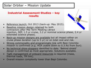
Solar orbiter – EUS instrument mechanical design. Tim Froud and Doug Griffin. Talk outline. Mechanical-thermal-optical considerations for the Primary Mirror Silicon Carbide Testbed Study Structural layout. Primary mirror WFE under Solar IR Loads.

E N D
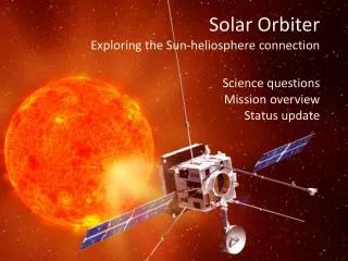
Solar orbiter – EUS instrument mechanical design Tim Froud and Doug Griffin
Talk outline • Mechanical-thermal-optical considerations for the Primary Mirror • Silicon Carbide Testbed Study • Structural layout
Primary mirror WFE under Solar IR Loads • The Solar radiation load will introduce thermal gradients in the Primary Mirror • Thermal stresses • Internal mirror temperature gradients • Possibly also from CTE mismatches • The thermal load will vary by roughly an order of magnitude during each orbit • Goal is to meet the optical performance during the encounter and during down link phases of the orbit • Mirror distortions will introduce distortions in the surface of the mirror which will reduce the spectral and spatial resolution of the instrument
Primary Mirror WFE Tolerance Estimates • Calculation based on encircled energy and are to be considered provisional • Given the Spectral and Spatial resolution requirements: • Derived requirement on PSF ~ 10um: • Mirror rms WFE: ~l/30 i.e. 21nm rms
NI Primary Mirror Distortion EstimatesModel Geometry 5mm 5mm Uniform heat load B/C 35kW/m2 Fixed Temperature B/C 25mm 40mm 5mm 10mm Axis of symmetry
NI Primary Mirror Distortion EstimatesMaterial Assumptions • Assume that the mirror is made from homogeneous Silicon Carbide • E=249GPa • Poission ratio: 0.16 • CTE: 2.7x10⁻⁶ m/m • Thermal conductivity: 127 W/m/K • Mirror is absorbing in the IR • Thermal interfaces have identical mechanical properties as Mirror • No interface stresses
NI Primary Mirror Distortion EstimatesTemperature Distribution
NI Primary Mirror Distortion EstimatesConclusions • The analysis has to be considered as a preliminary estimate • Optical • Thermal • Mechanical • Layout • Nonetheless: The conclusion is that the thermal control of the Primary Mirror will have to be considered in tandem with the overall instrument optical performance • It could be one of the largest challenges for the instrument design • Rastering of the instrument via the Primary mirror could be very difficult with the complexity of the thermal control
Primary Structure Material SelectionTest Bed Study • A study was carried out on a SiC based Optical Bench • Looked at the practical details of designing structural components in SiC • Very useful in terms of understanding: • Detailed manufacturing processes • Achievable tolerances • Mounting and interface designs • Lightweighting • Non-destructive Testing • Procurement of test-bed did not proceed due to cost • Promising outcome for Flight-build