Data Compression: Source Coding: Part II
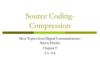
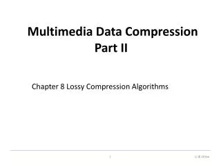
Chapter 8. Data Compression: Source Coding: Part II. Video Compression. Need a video (pictures and sound) compression standard for: Teleconferencing Digital TV broadcast Video telephone Movies Motion JPEG Compress each frame individually as a still image using JPEG.

Data Compression: Source Coding: Part II
E N D
Presentation Transcript
Chapter 8 Data Compression: Source Coding: Part II
Video Compression • Need a video (pictures and sound) compression standard for: • Teleconferencing • Digital TV broadcast • Video telephone • Movies • Motion JPEG • Compress each frame individually as a still image using JPEG. • Fails to take into consideration the extensive frame-to-frame redundancy present in all video sequences. • Hence the compression ratio is not satisfactory
H.261 • CCITT H.261 video codec for audiovisual services approved in 1990. • Applications for videophone and video conferencing over ISDN communication. • Bandwidth for transmission is at p x 64kbps. (1 B-ISDN channel = 64kbps.) • p = 1 or 2 suitable for videophone, desktop face-to-face visual communication. • p >= 6 ok for videoconferencing. • H.261 was developed for real-time encoding and decoding. • Symmetric encoding: compression delay ~ decompression delay • The maximum signal delay of both compression and decompression <= 60 ms.
CCITT Video Format for H.261 Y Cr Cb • Video images are transmitted in Y Cb Cr components. • Refresh rate: 30fps. • Two file formats : • CIF - Common Intermediate Format • QCIF - one Quarter of CIF Cr and Cb are usually subsampled
CCITT Video Format for H.261 (2) • If uncompressed, at 30 frames per second, • CIF requires (288x352x8 + 144x176x8 + 144x176x8) x 30 = 36.5Mbps • QCIF requires (144x176x8 + 72x88x8 + 72x88x8) x 30 = 9.1Mbps • ISDN can support 1x64kbps up to 30x64kbps = 2Mbps, therefore the bandwidth is insufficient and compression is required.
Compression Requirements • Desktop videophone applications • Channel capacity (p = 1) = 64Kbps. • QCIF at 10 frames/s still requires 3Mbps. • Required compression ratio is 3Mbps/64Kbps = 47 !! • Video conferencing applications • Channel capacity (p=10) = 640Kbps. • CIF at 30 frames/s requires 36.5Mbps. • Required compression ratio is 36.5Mps/640Kbps = 57 !! • Q: How much compression does JPEG give?
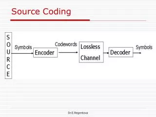
Coding Schemes • Source Coding • Deals with source material and yields results that are lossy, i.e., picture quality is degraded. • Intraframe coding: removes only spatial redundancy within a picture (e.g., JPEG). • Interframe coding: removes temporal redundancy between similar pictures in a sequence. • Entropy Coding • bit rate reduction by using the statistical properties of the signals (lossless).
Video Coding Algorithm • Combines intraframe and interframe coding to provide fast processing for on-the-fly video compression and decompression. • What is the purpose of I - frame? • To recover if there is error introduced during transmission I P P P I P P P
Video Coding Algorithm (2) • Frame types are CCIR 601 CIF and QCIF images with 4:2:0 subsampling. • 2 frame types: Intraframes (I-frames) and Interframes (P-frames). • Algorithm begins by coding an intraframe (I-frame) using JPEG-like method. • Each subsequent P-frame is encoded in terms of its predecessor using predictive interframe coding. • At least every 132th frame is coded as an I-frame to provide an accessing point and as a reference image for accurate decoding.
I-Frame • Macroblocks are 16x16 pixels on Y plane of original image. Consists of 4 Y blocks, 1 Cb block and 1 Cr block. • Quantization is by constant value for all DCT coefficients. • The “same” picture frame is also recovered and stored in the picture memory for interframe coding. Y1 Y2 Cr Cb 8 8 16 8 8 Y3 Y4 16
Inter Frame (P-Frame) Time = t+1 Time = t
+/- 8 to +/- 32 bits P-Frame (2) Best Match block • Previous image is called the reference image. • Image to be coded (predicted) is called thetarget image. • Interframe coding is based on prediction for each macroblock. Compare the reference against the target. • Determine the motion vector, i.e., the relative position of the reference block with respect to the target block, using some minimum mean-absolute-distance or mean-squared-error metrics. • Difference between the 2 blocks (if > certain threshold) is calculated and then sent to a JPEG-like encoder. If the difference < threshold, just send the motion vector.
Block Matching • The core of most video encoder is block matching. • Most time consuming part of the encoding process. (Target of optimization) • Takes place only on the luminance component of frames. • The search is usually restricted to a small search area centered around the position of the target block. • The maximum displacement is specified as the maximum number of pixels in the horizontal and vertical directions. • The search area needs not be square. Rectangular search areas are popular. (Why?) e.g., the CLM460xMPEG encoder uses a search area of about: +/- 100 (h) x +/- 55 (v) with half pixel accuracy. (Can you guess what half pixel accuracy is?)
Block Matching (2) • If the block size is b x b and the maximum displacements in the horizontal and vertical directions are dx and dy, then the search area = (2dx + b) x (2dy +b); the number of candidate blocks = (2dx + 1)(2dy + 1). • Considering every candidate block in the search area as a potential match is known as an Exhaustive Search, Brute Force Search, or Full Search. • That’s why we need hardware encoder!
Matching Criteria • A distortion function is used to quantify the similarity between the target block and the candidate blocks. • The distortion function should be easy to compute and should result in good matches. • Mean Absolute Difference (MAD) • Most popular • Mean Square Difference (MSD) • Results in slightly better matches
Matching Criteria (2) • Pel Difference Classification (PDC) • Compares the target block and the candidate block pixel by pixel. • A pixel pair is a match if the difference < certain threshold. • The greater the number of matching pixels, the better the match.
Matching Criteria (3) • Integral Projection (IP) • Calculated by summing the values of pixels from each column and each row of a block. • Can you think of an advantage of IP over the other distortion functions? • Essentially a low-pass filtering, hence less noise-sensitive.
Sub-optimal Searches • Principal of Locality • very good matches, if they exist, are likely to be found in the neighborhood of other good matches. • Example: Two-level hierarchical search:First examine a number of sparsely spaced candidate blocks from the search area and choose the best match as the center of a second finer search.
Sub-optimal Searches (2) • Three Step Search (TSS) • Given a maximum displacement d, set step size s = d/2. • Given a center [cx,cy], test nine points: [cx +/- 0 or s, cy +/- 0 or s]. • Take best match as new center, s = s/2 , repeat. • The first description of TSS uses a maximum displacement of +/- 6, hence the name.
Sub-optimal Searches (3) • Two Dimensional Logarithmic Search (TDL) • 1st block matching algorithm to exploit the quadrant monotonic model. • Given a center [cx, cy], test 5 points: [cx, cy] & [cx +/- s, cy +/- s]. • If [cx, cy] is the best match, s = s/2, repeat; • else if [a, b] is the best match, take it as the new center and repeat. • If s = 1, then all nine points around the center are tested. Take best match. • All points outside the search area are ignored.
Sub-optimal Searches (4) • Orthogonal Search Algorithm (OSA) • Given a center [cx, cy], test 3 points: [cx, cy], [cx-s, cy], [cx+s, cy]. • Let [a, b] be the best match, test 3 points: [a, b], [a, b+s], [a, b-s]. • Take best match as new center, set s = s/2, repeat. • One at a Time Search (OTS) • Locate the best match on the horizontal axis. Then starting with this point, find the best match in the vertical direction.
Sub-optimal Searches (5) • All previous searching strategies assume:Quadrant Monotonic • Assumes that the value of the distortion function increases as the distance from the point of minimum distortion increases. • i.e., no local minimum. • In other words, if there is local minimum, the previous searching algorithm may be trapped at the local minimum and never be able to find the global minimum. • This is also why they called sub-optimal not optimal
Dynamic Search Window • Concerns the rate at which the step size is reduced, and the problem of local minimum. • The extent to which the area of the search window decreases depends on the difference between the minimum distortion and the second lowest distortion. • e.g., use 3 reduction rates: fast (1/4), normal (1/2), slow (3/4). If the distortion difference is small, then the outcome of a stage of the algorithm was deemed inconclusive and so the step size was reduced only a little (slow); if the distortion is large, use fast reduction rate; in between, use normal rate. • Shown to result in fewer computations and better matches than the simple TSS.
Dependent Algorithms • Based on the assumption that motion of adjacent (spatial and temporal) blocks are correlated. • Use the motion vectors of neighboring blocks to calculate a prediction of the block’s motion, and this prediction is used as a starting point for the search. • Spatial Dependency • Take a weighted average of the neighboring blocks’ motion vectors. • Q: can we use all 8 neighbors? A: No! • The order in which blocks are matched restricts the choice of neighboring blocks that can be used.
Dependent Algorithms (2) • For example, you can weight the motion vectors of the following neighbors • Example. A multi-pass prediction process:Dark boxes indicate target block and lighter boxes represent the neighbors whose motion vectors assist the matching algorithm.
Dependent Algorithms (3) • To circumvent the problem of object boundaries (i.e. there is discontinuity of motion vectors), we can take a voting approach instead of averaging the neighbors’ motion vectors. • If the motion vectors of the neighboring blocks are not sufficiently uniform then the search for the target block might be carried out as normal, as though no spatial dependency was being exploited.
Dependent Algorithms (4) • Temporal Dependency • Similar predictions can be made by examining the motion of blocks in the previous frame. • Q: What is the difference in the assumptions of spatial dependency and temporal dependency? • Vector Coding • Up to 40% of the bits transmitted by a codec might be taken up with motion vector data. • It is found that Huffman techniques generally perform well in coding motion vectors.
Picture layer picture Hdr GOB data ............. GOB data Group of Block layer GOB Hdr MB data ............. MB data Macro Block layer MB Hdr Blk data .... Blk data Block layer TCOEFF ............. TCOEFF EOF H.261 Video Data Structure
H.261 Video Data Structure (2) • Picture Layer • CIF/QCIF • frame number/ time • Group-of-block Layer • quantizer information • 33 macro blocks / GOB => CIF:12 GOBs; QCIF: 3 GOBs. • Macro-block Layer • Intra/inter-frame • Block Layer • TCOEFF: DCT coefficients
MPEG • Reference: Didier Le Gall, "MPEG: A Video Compression Standard for Multimedia Applications," Communications of the ACM, April 1991, Vol.34, No.4, pp. 47-58. • What is MPEG? • A standard for delivery of audio and motion video. • By the Motion Picture Expert Group, ISO activity in 1993. • Official name: WG11 of JTC 1 / SC 29. • Further developments lead to standards of MPEG-2, and MPEG-4. MPEG-3 was dropped. • MPEG-1 targeted for VHS-quality on CD-ROM, i.e., about 320x240 + CD audio at 1.5Mbps.
MPEG (2) • MPEG-2 for higher resolution, CCIR 601 digital television quality video (720 x 480 x 30fps) @ 2-10 Mbps. MPEG-2 supports interlaced video formats, scaleable video coding for a variety of applications which need different image resolutions. • MPEG-3 for HDTV-quality video @ 40Mbps. Since MPEG-2 can be scaled to cover HDTV applications, MPEG-3 was dropped. • MPEG-4 for very-low-bit-rate applications.
MPEG (3) • Standard has 3 parts: • Video: based on H.261 and JPEG (1.5Mbps), optimized for motion-intensive video applications. (CR: 30-50:1) • Audio: based on MUSICAM technology (64/128/192 kbps). (CR: 5:1 to 10:1). • System: control interleaving of streams, synchronization.
MPEG Encoding Features • 4:2:0 subsampling. • Random access via I-frames • Fast forward/reverse searches • Reverse playback. • Audio-visual synchronization built into the data stream of audio/video. • Suitable for asymmetric compression. • Electronic publishing, games and entertainment require compression once and frequent decompression.
Temporal Dependency • Recall H.261 dependencies: I P P P I P P P
Temporal Dependency (2) • Prediction for the P-frames sometimes takes the advantage of bi-directional prediction. • For instance, the target image in the following takes both of the previous and future references for its derivation. target image
Temporal Dependency (3) • MPEG uses another frame type: B-frame. It is a bi-directional frame for searching in past and future frames for macro block. It also facilitates backward playback. I B B P B B P B B I
MPEG Frame Types • I-frames (Intra-coded frames) • Self-contained image frames, coded without the need for reference to other frames. • Use JPEG for I-frame encoding. • Lowest compression as no temporal redundancy exploited. • Provides points for random access in an MPEG stream. • P-frames (Predictive-coded frames) • Requires previous I, P frames for encoding and decoding. • Temporal redundancy: most image areas not changed over time but only get shifted. Only motion vectors and small difference of the macroblocks between the reference and target are encoded.
MPEG Frame Types (2) • P-Frame (cont’d) • Motion estimation: e.g., find a nearby macro-block MB such that the sum of the differences of the luminance component of MB and the target macro-block is minimum. • In most cases, predictive coding only makes sense for parts of the image and not for the whole image => not every macro-block in a P-frame is predictively encoded. Some of them are encoded in the I-frame style. (Consider a spinning disk.) • Since the motion vectors of adjacent macro blocks often differ only slightly, only the differences are encoded. Hi! Hi!
MPEG Frame Types (3) • B-frames (Bi-directionally predictive-coded frames) • Encoding the motion vector and difference of prediction based on the previous and following I and P frames. • Can use forward, backward prediction, or interpolation. • Higher compression ratio than I and P frames. • Cannot be accessed directly in a random fashion. • Two motion vectors are used (forward and backward). Interpolation of two reference blocks is “diffed” with the target block. • Never used as a reference frame (for the encoding of other frames). • Any disadvantages?
MPEG Frame Types (4) • D-frames (DC-coded frames) • Intra-frame encoded. • Only the DC coefficients are DCT-coded. AC components are neglected. • Used for fast forward or fast rewind modes.
B-frame Coding • Predictive coding for B-frames:
Choosing a Frame Type • I-Frame: good for direct access, bad for compression. • B-Frame: best for compression, add delay to the encoding process, more computationally expensive, needs a lot of buffer space. • P-Frame: good for compression. • Typical frame type sequence is ... IBBPBBPBBIBBPBBPBBI ... I B B P B B P B B I
Interframe Coding • Actual pattern is up to encoder, and need not be regular. • Bi-directional prediction: I B B P B B P • Transmitting order: 1, 4, 2, 3, 7, 5, 6, ... • Compression performance of different frame types
Recovery Ability • Due to the I-frame, MPEG stream can be resumed even some packets are lost. • The following is an experiment. I have truncated the middle part of the following movie, but it can still be played. • MPEG-1 is already been used in many applications, e.g VCD. original broken
MPEG-2 (2) • No D-Frame • Support interlaced video formats. • Support 5 audio channels (left, right, center, 2 surround channels). • Scaleable video coding for a variety of applications which need different image resolutions, such as video communications over ISDN networks using ATM.
MPEG-4 • Work is underway for very low bit rate audio-visual coding. MPEG-4 is a standard being developed for that. • New technologies required for model-based image coding for interactive multimedia and speech coding for low bit-rate communication. • i.e. More graphics + animation stuff. • Intended for compression of full-motion video consisting of small frames and requiring slow refreshments. • Up to video format of 176x144x10Hz, and data rate required is 9-40 Kbps. • To be used in interactive multimedia and video telephony.