Download

1 / 16
160 likes | 185 Views
This paper presents the production and testing processes of the CARLOS readout chip for the ALICE SDD Experiment, highlighting the design architecture, test criteria, and results achieved. The need for data compression due to high data volume is explained. The testing methods, equipment used, and test flow diagram are detailed, with a focus on functional and power tests. The production test results, including yield and rate, are summarized, showcasing the efficiency of the testing system at INFN in Bologna.

E N D
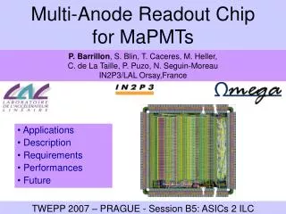
Production and Test of a readout chip for the ALICE SDD Experiment Samuele Antinori - Davide Falchieri Alessandro Gabrielli - Enzo Gandolfi – Massimo Masetti Department of Physics, University of Bologna I.N.F.N. Sezione di Bologna
Outline • SDD readout chain • The CARLOS chip • Why compression ? • Design Architecture • Test criteria and test set-up • Test results • Summary Samuele Antinori - INFN Bologna
SDD barrels Silicon Drift Detectors Number of detectors: 260 Samuele Antinori - INFN Bologna
SDD readout architecture SDD SDD SDD SDD PASCAL AMBRA CARLOS (data compression) GOL (Gigabit Optical Link) 40 MHz clock Programming & monitoring Data output & monitoring Samuele Antinori - INFN Bologna
CARLOS v5 ASIC (The readout chip designed and realized in Bologna ) • Features: • Total Die Size: 4x4 mm2. • 17k gates + four 256x9-bit SRAM blocks. • Radiation Tolerant, CERN 0.25 m CMOS . • Package: 14x14 mm, 100 pin TQFP • 1.4 mm height, 0.5 mm pitch CARLOS layout 100 pin TQFP Package Samuele Antinori - INFN Bologna
Why a compression chip ? Amount of data produced in a single event by SDD layers: 32.5 Mbytes Disk space reserved per event: 1.5 Mbytes compression ratio has to be 22 high compression ratio the compression algorithm has to complete its job within 2 ms. high execution speed high quality on reconstructed data data have to be used for analysis the algorithm has to be tunable high flexibility
2D Data Compression Reconstructed event Original event TH = 26, TL = 22 compression coefficient: 26.15 Samuele Antinori - INFN Bologna
Test of the Production 696 chips to be tested by Q4/2005 Samuele Antinori - INFN Bologna
Production Testbench at Bologna Labview for: • System automation • Graphical User Interface TLA 7PG2 Pattern Generator PXI Input pattern 40 MHz TTi QL355 TP power Power Supply TLA 7N2 Logic Analyzer DUT DG2020A 40MHz clock Clock Generator Mainframe TLA 715 Device Interface Board GPIB Samuele Antinori - INFN Bologna
Production Testing Lab Power Supply Clock Generator TLA 715 mainframe • Production Tester operated by one technician. • Manual chip handling. • Testing times per chip • Testing: 7 min • Handling: 30 secs • Total: 7,50 min Samuele Antinori - INFN Bologna
Test Flow Diagram Apply Power to DUT DC Measurements: Idd (total current consumption) Static (DC) Tests Sweep Power to DUT: It varies from 2,1V to 2,7V Fail Pass Sweep Power to DUT Frequency to DUT: It varies from 39 to 41 MHz Apply Frequency test Input Pattern: Define voltage levels for the input pattern. Input Pattern Functional Tests • Functional Tests: • R/W all JTAG registers • Memory test • Internal BIST • 2D compression test Acquire Output Bus Fail Pass No • Data checking: • Data acquired are compared with the expected values. • Data outputs are decoded and reconstructed events are compared to the original ones. Last pattern ? Yes Release Power to DUT REJECT ACCEPT Samuele Antinori - INFN Bologna
CARLOS functional test • Memory test for 4 256x9-bit SRAM blocks: • 2 input patterns of 120 kwords write A and 5 hex codes in each 9-bit SRAM cell. • 2D compression test: • 9 different test patterns of 120 kwords are used for 2D compression test with different threshold and anode length values. • JTAG test: • 2 input patterns of 12 kwords read / write A and 5 hex codes in all JTAG registers of CARLOS. • 1 input pattern of 40 kwords drives the three output JTAG ports. • Control signal test: • 2 different pattern of 120 kwords are used for testing CARLOS control signals: abort, flush, prepulse, … CARLOS v5 schematic block Observations: - every chip that passed the BIST successfully also passed the functional tests as well. Samuele Antinori - INFN Bologna
Graphical User Interface • Easy to Use • No technical expertise needed by the operator • Report file is generated for the bad chips Samuele Antinori - INFN Bologna
CARLOS power test results Values of Idd of 289 good CARLOS chips: Samuele Antinori - INFN Bologna
Production Test results • 325 chip tested (28/9/2005) • Production Yield: 89 % • Production rate: 8 chips/hour • Daily schedule: 8 hours/day for 2 day at week Samuele Antinori - INFN Bologna
Summary • CARLOS ASIC production (696), packaging (TQFP 100-pin 0.5 mm pitch) and test: so far 325 tested with 89% yield. • A mass production testing system was required to test 260 CARLOS chip for 260 SDD modules (this number is now available) • the system is working efficiently at INFN in Bologna • Typical testing time is 450 sec Samuele Antinori - INFN Bologna