Download
1 / 39
390 likes | 639 Views
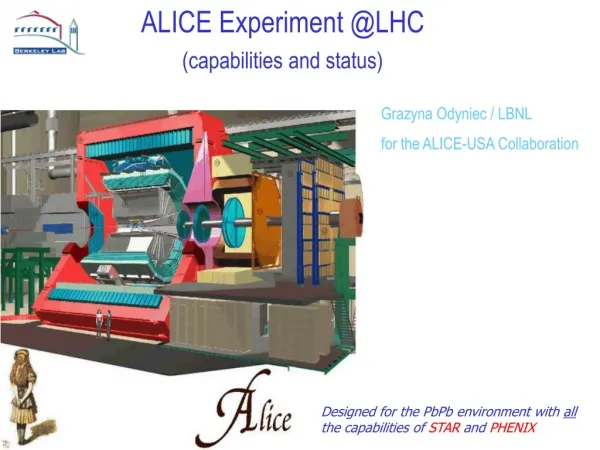
ALICE experiment. Detectors Photon spectrometer Central tracking detectors ITS, TPC, TRD Particle identification Data acquisition and trigger. ALICE - general view. In action. Full simulation of ALICE (shown is a 2 0 q slice) with Pb-Pb events at max multiplicity. For full event:.

E N D
ALICE experiment • Detectors • Photon spectrometer • Central tracking detectors • ITS, TPC, TRD • Particle identification • Data acquisition and trigger
In action... • Full simulation of ALICE (shown is a 20q slice) with Pb-Pb events at max multiplicity For full event:
The ALICE Inner Tracking System SSD • 6 Layers, three technologies (keep occupancy ~constant ~2%) • Silicon Pixels (0.2 m2, 9.8 Mchannels) • Silicon Drift (1.3 m2, 133 kchannels) • Double-sided Strip Strip (4.9 m2, 2.6 Mchannels) SDD SPD Lout=97.6 cm Rout=43.6 cm
Tracking in the ITS:PbPb central event,q slice83o-87o • - primary vertex - secondary vertices => for Hyperons => for Charm and Beauty • - dE/dx for particle identification (@low momenta) • - improve TPC momentum resolution • - stand-alone tracking for low-Pt particles
11mm SMD component 7 7 7 7 6 6 5 5 4 235µm PIXEL_BUS 3 Aluminium 2 2 1 1 Polyimide PIXEL DETECTOR Glue 600µm READOUT CHIP 1 ANALOG_GND 25µ 2 ANALOG_ POWER 25µ 3 HORIZONTAL LINES 10µ 4 VERTICAL LINES 5µ 5 DIGITAL_POWER 25µ 6 DIGITAL_GND 25µ 7 RES + CAPA PADS 15µ ? CARBON FIBER SUPPORT COOLING TUBE ALICE Silicon Pixel Detector (SPD) 2mm => 150µm +200µm final ?
ALICE Pixel Chip • 50 µm x 425 µm pixel cell • 8192 cells: 32 columns x 256 rows • Active area: 12.8 x 13.6 mm • Mixed signal (analogue, digital) • Commercial 0.25µm CMOS process • Radiation tolerant design • (enclosed gates, guard rings) • 13 million transistors • 10 MHz clock • ~100 µW/channel • Prototype works to ALICE specs! PR/GS/PG/LHC Pys. & Det., Chia
detector final tender completed, production starts early ‘02 47 detectors pre-production confirms ~ 70% yield Calibration methods compensate for T variations and inhomogeneity of Si t =0 Anode number Drift time (25 ns) SDD Charge injectors event Positions of HV dividers
FEE final prototype (PASCAL) design review passed, eng. run 2Q 2002 event buffer prototype (AMBRA) design review passed, eng. run 2Q 2002 Analogue memory Preamplifiers ADCs SDD: frontend
SDD electronic chain in beam test Noise levels • Test of final detectors + electronics with beam @ PS One MIP Signal vs. drift distance
SSD • R&D essentially complete • Detector tender completed • Three companies share the 1800 detector production • New, radtol FEE chip prototype works fine • very fast development (<one year) by Strasbourg, only minor adjustments needed • Eng. run first half of 2002 • Hybrid design defined • RO electronics and controls being finalized • NOW: tune production/test/assembly procedures and go into construction
SSD assembly • TAB bonding on Al/polyimide flexible microcables • Microcables serve as multilayer hybrids • Known Good Die principle to be applied • Microcables are produced in one of the collaborating institutes (Kharkov, Ukraine) • Assembly has been proven in labs and in industry => now setting up the assembly chains (France, Italy, Finland, The Netherlands) to produce the 2000 modules and 72 ladders • A similar assembly procedure has been developed for the STAR SSD, involving some of the same groups, and applied to ~ 400 detector modules
SDD/SSD Supports • Carbon ladders SSD (St. Petersburg, Russia) • ~ 80 produced • 100% of strip ladders • now spares and SDD • next: assembly of ancillary components
TPC layout GAS VOLUME 88 m3 DRIFT GAS 90% Ne - 10%CO2 E E 88us 510 cm Readout plane segmentation 18 trapezoidal sectors each covering 20 degrees in azimuth
TPC status: Field Cage BEING MANUFACTURED! Hand lay-up of composite structure Cylinders are fabricated from three 120-degree-‘panels’ glued together (lashing). Production has started in September 2001
R&D completed, in production Inner RO Chambers 1/4 production done (GSI, Heidelberg, later Bratislava) Out. RO Chambers start prod. 1st Q02 TPC status: RO chambers Pad Plane: 5504 pads (4x7.5 mm2) CLOSE-UP ON THE PADS In assembly CONNECTOR SIDE
Digital Circuit TPC status: electronics FEC (Front End Card) - 128 CHANNELS (CLOSE TO THE READOUT PLANE) DETECTOR Power consumption: < 40 mW / channel L1: 5ms 200 Hz 8 CHIPS x 16 CH / CHIP 8 CHIPS x 16 CH / CHIP drift region 88ms L2: < 100 ms 200 Hz • Ion tail cancellation performed digitally • Commercial ADC integrated on custom digital chip => very substantial saving in power, complexity and $! • All being prototyped, engineering runs mid 2002 gating grid PASA ADC RAM anode wire DDL (4096 CH / DDL) 570132 PADS CUSTOM IC (CMOS 0.35mm) pad plane CUSTOM IC (CMOS 0.25mm ) CSA SEMI-GAUSS. SHAPER 1 MIP = 4.8 fC S/N = 30 : 1 DYNAMIC = 30 MIP • BASELINE CORR. • TAIL CANCELL. • ZERO SUPPR. 10 BIT < 10 MHz MULTI-EVENT MEMORY GAIN = 12 mV / fC FWHM = 190 ns
DIGITAL PROCESSOR & CONTROL LOGIC 8 ADCs 8 ADCs MEMORY TPC electronics:ALICE TPCE READOUT CHIP (ALTRO) ADC Adaptive Baseline Correct. I Tail Cancel. Adaptive Baseline Correct. II Data Format. Multi-Event Memory + - 10- bit 20 MSPS 11- bit CA2 arithmetic 18- bit CA2 arithmetic 11- bit arithmetic 40-bit format 40-bit format SAMPLING CLOCK 20 MHz READOUT CLOCK 40 MHz 0.25 mm (ST) area:64mm2 power:29 mW / ch SEU protection DIGITAL TAIL CANCELLATION PERFORMANCE ADC counts ADC counts Time samples (170 ns)
Dimuon Spectrometer • Study the production of the J/Y, Y', U, U' and U'' versus the centrality of the reaction • Resolution of 70 MeV on the J/Y and 100 MeV on the U • overall performance improved with updated detector design (TDR addendum) Plot of 1-month Pb run result, showing the good separation of the various resonances, allowing a systematic study of Debye screening • The spectrometer is taking shape: • Production of magnet started (yoke and coil) • Trigger chambers final prototype tested in GIF with final electronics • Begin of detector production in 2002 The absorber design is being revised to try to overcome a major cost overrun
main aims: high pt (> 1 GeV) electron identification trigger on high pt (>3 GeV) electrons and jets physics: heavy quarks (c, b), quarkonia (J/Psi, Y), jets detector: fiber radiator to induce TR (g > 2000) large (800 m2), high granularity (> 1M ch.) drift detectors online trigger electronics to select stiff tracks (measure sagitta) Transition Radiation Detector(TRD) x6
ALICE Photon Spectrometer (PHOS) • Physics • Thermal radiation • High pt physics • Tagged jets • Detector • Dimensions: h 0.12, 100(18 m2) at radius R 4.6 m • PbWO4 crystals, X0 = 0.89 cm, lint = 19.5 cm, Moliere radius: 2.0 cm • Granularity: 2.22.2 cm2 (Dh Dj 0.005 0.005), length: 18 cm • p0 identified from 3 to > 50 GeV/c • Energy resolution 2% above 3 GeV/c • Starting pre-production
V01.6 < |h| < 3.9Interaction trigger, centrality trigger and beam-gas rejection. Two arrays of 72 scintillator tiles readout via fibers Forward detectors PMD T0L FMD Measure Multiplicity and h dist. over 1.6 < h < 3, -5.4 < h < -1.6 Silicon pad detector disks (slow readout) with 12k analog channels (occ.>1) T0R2.6 < |h| < 3.3 T0 for the TOF (~ 50 ps time res.) Two arrays of 12 quartz counters. Also backup to V0
ALICE ZDC Calorimeters ZP ZN Aim: determination of the impact parameter of the collision by measuring the energy carried by the spectator nucleons Where: hadronic calorimeters at ~ 116 m from IP e.m. calorimeter at ~ 8 m from IP Central events selected with both: -Energyin hadronic calorimeters < E0 -Energy in e.m. calorimeter >E1 Ehad vs Ee.m. E0 E1
Trigger Detectors: Micro Channelplate - Zero-Degree Cal. - Muon Trigger Chambers - Transition Radiation Detector F F E E E E RORC RORC RORC RORC RORC RORC RORC RORC RORC RORC RORC RORC RORC RORC RORC RORC RORC RORC RORC RORC PCI PCI PCI PCI LDC/FEDC LDC/FEDC LDC/FEDC LDC/FEDC NIC NIC NIC NIC NIC NIC NIC NIC NIC NIC NIC NIC NIC NIC NIC NIC NIC NIC NIC NIC NIC NIC NIC NIC NIC NIC NIC NIC NIC NIC NIC NIC NIC NIC NIC NIC NIC NIC NIC NIC NIC NIC NIC NIC NIC NIC NIC NIC PCI PCI PCI PCI PCI PCI PCI PCI MEM CPU MEM CPU MEM CPU MEM CPU MEM CPU MEM CPU MEM CPU MEM CPU MEM CPU MEM CPU MEM CPU MEM CPU MEM CPU MEM CPU MEM CPU MEM CPU MEM CPU MEM CPU MEM CPU MEM CPU MEM CPU MEM CPU MEM CPU MEM CPU MEM CPU MEM CPU MEM CPU MEM CPU MEM CPU MEM CPU MEM CPU MEM CPU MEM CPU MEM CPU MEM CPU MEM CPU MEM CPU MEM CPU MEM CPU MEM CPU MEM CPU MEM CPU MEM CPU MEM CPU MEM CPU MEM CPU MEM CPU MEM CPU LDC/L3CPU LDC/L3CPU LDC/L3CPU LDC/L3CPU LDC/L3CPU LDC/L3CPU LDC/L3CPU LDC/L3CPU PCI PCI PCI PCI PCI PCI PCI PCI PCI PCI PCI PCI PCI PCI PCI PCI PCI PCI PCI PCI PCI PCI PCI PCI PCI PCI PCI PCI PCI PCI PCI PCI PCI PCI PCI PCI GDC/L3CPU GDC/L3CPU GDC/L3CPU GDC/L3CPU GDC/L3CPU GDC/L3CPU GDC/L3CPU GDC/L3CPU GDC/L3CPU GDC/L3CPU GDC/L3CPU GDC/L3CPU GDC/L3CPU GDC/L3CPU GDC/L3CPU GDC/L3CPU GDC/L3CPU GDC/L3CPU GDC/L3CPU GDC/L3CPU GDC/L3CPU GDC/L3CPU GDC/L3CPU GDC/L3CPU GDC/L3CPU GDC/L3CPU GDC/L3CPU GDC/L3CPU GDC/L3CPU GDC/L3CPU GDC/L3CPU GDC/L3CPU GDC/L3CPU GDC/L3CPU GDC/L3CPU GDC/L3CPU Particle Identification Photon Spectrometer Inner Tracking System Muon Tracking Chambers 36 TPC Sectors Trigger Decisions Detectorbusy F E E F E E F E E F E E F E E F E E DD L Tr ig g er Data L0 Trigger L1 Trigger L3/DAQ/Processor Farm Switch Fabric L2 Trigger EDM LDC: Local Data Concentrator; Software running on standard CPU FEDC: Front-End Digital Computer - generic commercial off-the-shelf CPU RORC: ReadOut Receiver Card (PCI based) L3CPU: L3 Processor - generic commercial off-the-shelf CPU GDC: Global Data Concentrator - generic commercial off-the-shelf CPU NIC: Network Interface Card Computer centre S w i t c h DAQ and Trigger P D S P D S P D S P D S
Data volume and event rate TPC detector data volume = 300 Mbyte/event, data rate = 200 Hz bandwidth 60 Gbyte/sec front-end electronics 15 Gbyte/sec realtime data compression & pattern recognition PC farm = 1000 clustered SMP parallel processing DAQ – event building < 2 Gbyte/sec < 1.2 Gbyte/sec permanent storage system
HLT trigger • Trigger rates ptsingle > 1 GeV/c ptsingle > 0.8 GeV/c ptpair > 3 GeV/c J//event 0.007 0.0006 background/event 0.39 0.15 HLT system TPC @ 150 Hz TRD @ 1kHz Online track reconstruction: 1) selection of e+e—pairs (ROI) 2) analysis of e+e—pairs (event rejection)