Download

1 / 15
150 likes | 372 Views
Delay Testing of Digital Circuits. Vishwani D. Agrawal Agere Systems, Murray Hill, NJ 07974 USA va@agere.com http://cm.bell-labs.com/cm/cs/who/va January 16, 2002. Delay Test Definition.

E N D
Delay Testing of Digital Circuits Vishwani D. Agrawal Agere Systems, Murray Hill, NJ 07974 USA va@agere.com http://cm.bell-labs.com/cm/cs/who/va January 16, 2002 Agrawal: Delay testing
Delay Test Definition • A circuit that passes delay test must produce correct outputs when inputs are applied and outputs observed with specified timing. • For a combinational or synchronous sequential circuit, delay test verifies the limits of delay in combinational logic. • Delay test problem for asynchronous circuits is complex and not well understood. Agrawal: Delay testing
Digital Circuit Timing Input Signal changes Output Observation instant Transient region Inputs Comb. logic Synchronized With clock Outputs time Clock period Agrawal: Delay testing
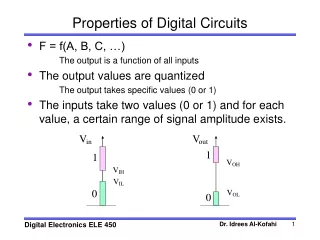
Circuit Delays • Switching or inertial delay is the interval between input change and output change of a gate: • Depends on input capacitance, device (transistor) characteristics and output capacitance of gate. • Also depends on input rise or fall times and states of other inputs (second-order effects). • Approximation: fixed rise and fall delays (or min-max delay range, or single fixed delay) for gate output. • Propagation or interconnect delay is the time a transition takes to travel between gates: • Depends on transmission line effects (distributed R, L, C parameters, length and loading) of routing paths. • Approximation: modeled as lumped delays for gate inputs. Agrawal: Delay testing
Event Propagation Delays Single lumped inertial delay modeled for each gate PI transitions assumed to occur without time skew Path P1 1 3 1 0 2 4 6 P2 1 2 3 0 P3 5 2 0 Agrawal: Delay testing
Robust Test • A robust test guarantees the detection of a delay fault of the target path, irrespective of delay faults on other paths. • A robust test is a combinational vector-pair, V1, V2, that satisfies following conditions: • Produce real events (different steady-state values for V1 and V2) on all on-path signals. • All on-path signals must have controlling events arriving via the target path. • A robust test is also a non-robust test. • Concept of robust test is general – robust tests for other fault models can be defined. Agrawal: Delay testing
A Five-Valued Algebra • Signal States: S0, U0 (F0), S1, U1 (R1), XX. • On-path signals: F0 and R1. • Off-path signals: F0=U0 and R1=U1. Input 1 Input 1 S0 U0 S1 U1 XX S0 S0 S0 S0 S0 S0 U0 S0 U0 U0 U0 U0 S1 S0 U0 S1 U1 XX U1 S0 U0 U1 U1 XX XX S0 U0 XX XX XX S0 U0 S1 U1 XX S0 S0 U0 S1 U1 XX U0 U0 U0 S1 U1 XX S1 S1 S1 S1 S1 S1 U1 U1 U1 S1 U1 U1 XX XX XX S1 U1 XX AND OR Input 2 Input 2 Input S0 U0 S1 U1 XX S1 U1 S0 U0 XX Ref.: Lin-Reddy IEEETCAD-87 NOT Agrawal: Delay testing
Non-Robust Test Generation Fault P2 – rising transition through path P2 has no robust test. C. Set input of AND gate to propagate R1 to output D. R1 propagates through OR gate since off-path input is U0 XX U1 R1 R1 Path P2 R1 A. Place R1 at path origin R1 R1 U1 U0 Non-robust test requires Static sensitization: S0=U0, S1=U1 XX U0 B. Propagate R1 through OR gate; interpreted as U1 on off-path signal; propagates as U0 through NOT gate Non-robust test: U1, R1, U0 Agrawal: Delay testing
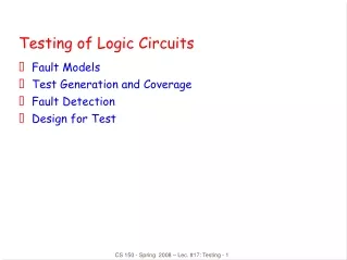
Path-Delay Faults (PDF) • Two PDFs (rising and falling transitions) for each physical path. • Total number of paths is an exponential function of gates. Critical paths, identified by static timing analysis (e.g., Primetime from Synopsys), must be tested. • PDF tests are delay-independent. Robust tests are preferred, but some paths have only non-robust tests. • Three types of PDFs (Gharaybeh, et al., JETTA (11), 1997): • Singly-testable PDF – has a non-robust or robust test. • Multiply-testable PDF – a set of singly untestable faults that has a non-robust or robust test. Also known as functionally testable PDF. • Untestable PDF – a PDF that is neither singly nor multiply testable. • A singly-testable PDF has at least one single-input change (SIC) non-robust test. Agrawal: Delay testing
Slow-Clock Test Combinational circuit Output latches Input latches Input test clock Output test clock Rated clock period Test clock period Input test clock Output test clock V2 applied V1 applied Output latched Agrawal: Delay testing
Normal-Scan Test V2 states generated, (A) by one-bit scan shift of V1, or (B) by V1 applied in functional mode. Result latched V2 PIs applied V1 PIs applied PI Combinational circuit PO Result scanout Scanin V1 states Gen. V2 states Path tested t CK TC SCAN- OUT Slow clock Rated CK period SFF TC (A) Normal mode Scan mode Scan mode SFF SCANIN Slow CK period CK TC TC (B) CK: system clock TC: test control SFF: scan flip-flop Scan mode Normal mode Scan mode Agrawal: Delay testing
Variable-Clock Sequential Test Off-path flip-flop PI PI PI PI PI PI 0 1 T n T n+1 1 1 T 1 T n-2 T n+m T n-1 1 2 2 2 0 D PO PO PO PO PO PO Path activation (rated Clock) Fault effect propagation sequence (slow clock) Initialization sequence (slow clock) Note: Slow-clock makes the circuit fault-free in the presence of delay faults. Agrawal: Delay testing
At-Speed Test • At-speed test means application of test vectors at the rated-clock speed. • Two methods of at-speed test. • External test: • Vectors may test one or more functional critical (longest delay) paths and a large percentage (~100%) of transition faults. • High-speed testers are expensive. • Built-in self-test (BIST): • Hardware-generated random vectors applied to combinational or sequential logic. • Only clock is externally supplied. • Non-functional paths that are longer than the functional critical path can be activated and cause a good circuit to fail. • Some circuits have initialization problem. Agrawal: Delay testing
Timing Design & Delay Test • Timing simulation: • Critical paths are identified by static (vector-less) timing analysis tools like Primetime (Synopsys). • Timing or circuit-level simulation using designer-generated functional vectors verifies the design. • Layout optimization: Critical path data are used in placement and routing. Delay parameter extraction, timing simulation and layout are repeated for iterative improvement. • Testing: Some form of at-speed test is necessary. PDFs for critical paths and all transition faults are tested. Agrawal: Delay testing
Conclusion • Path-delay fault (PDF) models distributed delay defects. It verifies the timing performance of a manufactured circuit. • Transition fault models spot delay defects and is testable by modified stuck-at fault tests. • Variable-clock method can test delay faults but the test time may be long. • Critical paths of non-scan sequential circuits can be effectively tested by rated-clock tests. • Delay test methods (including BIST) for non-scan sequential circuits using slow ATE require investigation: • Suppression of non-functional path activation in BIST. • Difficulty of rated-clock PDF test generation. • Long sequences of variable-clock tests. Agrawal: Delay testing