Download

1 / 15
150 likes | 325 Views
Work in teams of two!. Using the Board of Education Breadboard and Your Multimeter. ENGR 120. Your Multimeter. pincer clips – good for working with Boe-Bot wiring. probes. (push these onto probes). leads. turn knob to what you would like to measure.

E N D
Work in teams of two! Using the Board of Education Breadboard and Your Multimeter ENGR 120
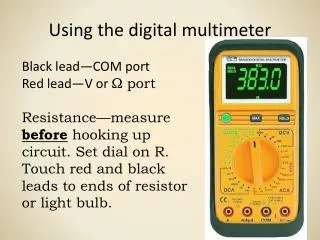
Your Multimeter pincer clips – good for working with Boe-Bot wiring probes (push these onto probes) leads turn knob to what you would like to measure You will use the multimeter to understand and troubleshoot circuits, mostly measuring DC voltage, resistance and DC current.
Measure Vin Vin will be the same as your power supply voltage. For the case below, 4 AA batteries are used resulting in approximately 6 V (5.79 V to be more exact). Vin = power supply voltage Vss = ground (negative side of battery) Switch to DC Volts
Measure Vdd Vdd will always be around 5V (it is 4.94 V here). A voltage regulator on the Board of Education reduces this voltage from Vin down to ~ 5V. The Boe-Bot operates on 5V DC. Vdd ~ 5V Vss = ground (negative side of battery)
Select Resistors Find the 470W and the 10kW resistors from your Boe-Bot kit. Example: 470W resistor: 4 = yellow 7 = violet Add 1 zero to 47 to make 470, so 1 = brown So, 470 = yellow, violet, brown Now, find the 10kW resistor. Diagram from the Parallax Robotics book
Check Resistance of Resistors R ~ 470W set multimeter to measure W
Connecting an LED LED = Light Emitting Diode Diagram from the Parallax Robotics book Electricity can only flow one way through an LED (or any diode).
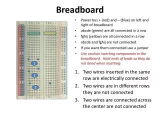
Building an LED Circuit Vdd = LED These circuit diagrams are equivalent these holes are “connected” Vdd = 5V holes in this direction are not connected Diagram from the Parallax Robotics book
Replace the 470W Resistor with the 10kW Resistor What happens and Why?? ANSWER: The smaller resistor (470W) provides less resistance to current than the larger resistor (10kW). Since more current passes through the smaller resistor, more current also passes through the LED making it brighter. What would happen if you forgot to put in a resistor? You would probably burn up your LED.
Connect the Resistor to Pin 12 (P12) Diagram from the Parallax Robotics book Enter and run the following PBASIC program: ' {$STAMP BS2} ' {$PBASIC 2.5} DO HIGH 12 PAUSE 500 LOW 12 PAUSE 500 LOOP
How the Program Works Causes pin 12 to output a constant 5V (Vdd) wait 500 ms infinite loop Causes pin 12 to output a constant 0V (Vss) Wait 500 ms ' {$STAMP BS2} ' {$PBASIC 2.5} DO HIGH 12 PAUSE 500 LOW 12 PAUSE 500 LOOP Diagram from the Parallax Robotics book HIGH = 5V and LOW = 0V (Always!!!!)
Now Experiment on Your Own! • Try changing the time to 1.5 seconds on and 1 second off • Connect the resistor to pin 8 and change the program to match • Blink out SOS in Morse code (dot-dot-dot-dash-dash-dash-dot-dot-dot) • three short pulses (0.25 seconds each) followed by . . . • three long pulses (0.75 second each) followed by . . . • three short pulses (0.25 seconds each) followed by . . . • a brief pause (1 second) • repeat a through d using an infinite loop Show your instructor when you have completed exercise (3).
Another Way to Make the LED Blink Enter and run the following PBASIC program: Causes pin 12 to output a constant 5V for . . . ' {$STAMP BS2} ' {$PBASIC 2.5} DO PULSOUT 12, 65000 PAUSE 2000 LOOP 65000 x 2ms = 130000 ms = 0.13 s Wait 2000 ms = 2 s Diagram from the Parallax Robotics book
Find the PULSOUT Command Using PBASIC Help Now, you change the program to make the LED blink on for a duration of 0.01 seconds and off for a duration of 0.1 seconds. Show your instructor.