Using a Multimeter
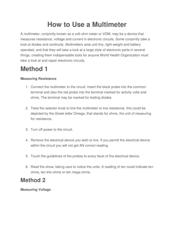
Using a Multimeter. What is a multimeter?. A multimeter is a devise used to measure voltage, resistance and current in electronics & electrical equipment It is also used to test continuity between to 2 points to verify if there is any breaks in circuit or line

Using a Multimeter
E N D
Presentation Transcript
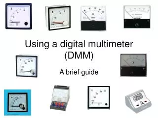
What is a multimeter? • A multimeter is a devise used to measure voltage, resistance and current in electronics & electrical equipment • It is also used to test continuity between to 2 points to verify if there is any breaks in circuit or line • There are two types of multimeter Analog & Digital • Analog has a needle style gauge • Digital has a LCD display (Referenced during this PPT)
There are 2 styles of multimeters Switched Manually switch between ranges to get most accurate reading. Auto RangeSwitches between ranges automatically for best reading. Both of these styles work the same
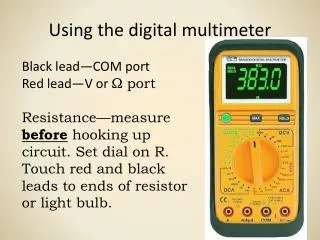
Meter leads • Red meter leadIs connected to Voltage/Resistance or amperage portIs considered the positive connection • ProbesAre the handles used to hold tip on the tested connection • TipsAre at the end of the probe and provides a connection point • Black meter leadIs always connected to the common port Is considered the negative connection
Display & Dial Settings • Digital DisplayShows measured value. • Meter DialTurn dial to change functions.Turn dial to OFF position after use. • Panel IndicatorShows each function and setting range to turn dial to. • Probe ConnectionsSpecific for each function.
Common DMM Symbols ~ AC Voltage Ground --- DC Voltage ( Capacitor Hz Hertz mF MicroFarad + Positive m Micro Negative m Milli W Ohms M Mega * Diode K Kilo ))) Audible Continuity OL Overload These symbols are often found on multimeter and schematics. They are designed to symbolize components and reference values.
Measuring Voltage • Voltage (V) is the unit of electrical pressure; one volt is the potential difference needed to cause one amp of current to pass through one ohm of resistance • Voltage is broke up into 2 sections AC & DC Alternating Current (AC) is house voltage (110vac) Direct Current (DC) is battery voltage (12vdc) • On switched meters use one value higher than your expected value • Be very careful to not touch any other electronic components within the equipment and do not touch the tips to each other while connected to anything else • To measure voltage connect the leads in parallel between the two points where the measurement is to be made. The multimeter provides a parallel pathway so it needs to be of a high resistance to allow as little current flow through it as possible
Measuring Voltage 9.3vdc
Measuring Resistance and Continuity • Resistance (W) is the opposition to current • Resistance is measured in Ohm's • Disconnect power source before testing • Remove component or part from system before testing • Measure using lowest value, if OL move to next level • Testing for continuity is used to test to verify if a circuit, wire or fuse is complete with no open • Audible continuity allows an alarm if circuit is complete • If there is no audible alarm resistance of 1ohm to .1ohm should be present
Measuring Resistance 100W
Measuring Continuity .5W Fuse 5 amp
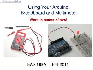
Measuring Current • Current (amps) is the flow of electrical charge though a component or conductor • Current is measured in amps or amperes • Disconnect power source before testing • Disconnect completed circuit at end of circuit • Place multimeter in series with circuit • Reconnect power source and turn ON • Select highest current setting and work your way down.
Measuring Current 1.1amps
Review • A meter capable of checking for voltage, current, and resistance is called a multimeter, • When measuring Voltage the multimeter must be connected to two points in a circuit in order to obtain a good reading. Be careful not to touch the bare probe tips together while measuring voltage, as this will create a short-circuit! • Never read Resistance or test for Continuity with a multimeter on a circuit that is energized. • When measuring Current the multimeter must be connected in a circuit so the electrons have to flow through the meter • Multimeters have practically no resistance between their leads. This is intended to allow electrons to flow through the meter with the least possible difficulty. If this were not the case, the meter would add extra resistance in the circuit, thereby affecting the current