Breadboard
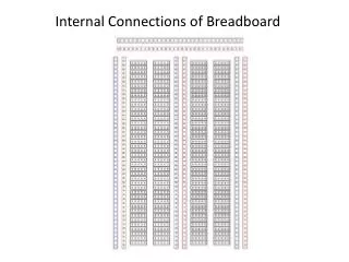
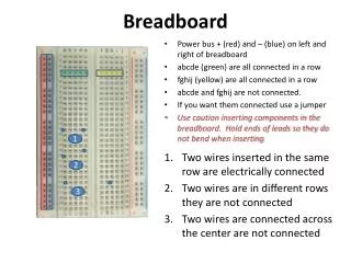
Breadboard. Power bus + (red) and – (blue) on left and right of breadboard a bcde (green) are all connected in a row f ghij (yellow) are all connected in a row a bcde and f ghij are not connected. If you want them connected use a jumper

Breadboard
E N D
Presentation Transcript
Breadboard Power bus + (red) and – (blue) on left and right of breadboard abcde(green) are all connected in a row fghij(yellow) are all connected in a row abcdeand fghijare not connected. If you want them connected use a jumper Use caution inserting components in the breadboard. Hold ends of leads so they do not bend when inserting Two wires inserted in the same row are electrically connected Two wires are in different rows they are not connected Two wires are connected across the center are not connected 1 2 3
Series Components in a Circuit (Head to Tail) 2 Connect the voltage source positive connector to the + bus Add a jumper from the + bus to the row for the first component Insert the first component so one end is in the same row as the jumper Insert the second component in row ending the first component (tail to head) Jumper the row ending the second component to the – bus Connect the voltage source negative connector to the – bus Turn on voltage source - circuit is complete to energize circuit 3 4 5 1 6
Parallel Components (Head to Head) 2 Connect the voltage source positive connector to the + bus Add a jumper from the + bus to the row for the first component Insert the first component so one end is in the same row as the jumper Insert the second component in same row with the first component Jumper the row ending the second component to the – bus Complete the circuit by connecting the voltage source negative connector to the – bus Turn on voltage source when circuit is complete to energize circuit 3 4 5 1 6
Use DVM to measure Voltage or Ohms DVM 1 Connect the probe (red) to the breadboard start row of the component to be measured Use a jumper if the probe does not fit in the breadboard Connect the other probe (black) to the breadboard end row to be measured Use a jumper if the probe does not fit in the breadboard Set the digital volt meter to measure volts DC Use this setup to measure resistance. Set the multi-meter to measure Ohms. Note: you can never measure resistance when the circuit is energized 2 5 4 3
Use DVM to measure Current Multi-meter must be inserted in series in the circuit to measure current Move the probe to the mA connector Remove the jumper connection from the voltage source negative connection Connect the probe to the – bus on the breadboard (Tip: you may need to use jumpers if the probe does not fit n the breadboard) Connect the common probe to the voltage source negative connection Set the meter to measure mA DC (mode button if necessary) 1 5 3 4 2