Download
1 / 33
330 likes | 352 Views
Explore the fundamentals of MAC addresses, ARP protocol, and data link layer protocols in computer networking. Learn how devices communicate using MAC and IP addresses.

E N D
CS 1652 Jack Lange University of Pittsburgh
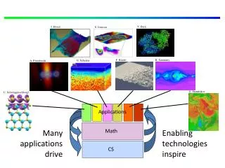
MAC Addresses and ARP • 32-bit IP address: • network-layer address • used to get datagram to destination IP subnet • MAC (or LAN or physical or Ethernet) address: • function:get frame from one interface to another physically-connected interface (same network) • 48 bit MAC address (for most LANs) • burned in NIC ROM, also sometimes software settable 5: DataLink Layer
LAN addresses and ARP each adapter on LAN has unique LAN address Broadcast address = FF-FF-FF-FF-FF-FF 1A-2F-BB-76-09-AD LAN (wired or wireless) adapter 71-65-F7-2B-08-53 58-23-D7-FA-20-B0 0C-C4-11-6F-E3-98 Link Layer and LANs
LAN Address (more) • MAC address allocation administered by IEEE • Manufacturer buys portion of MAC address space (to assure uniqueness) • Analogy: • (a) MAC address: Your Social Security Number • (b) IP address: Your postal address • MAC flat address ➜ portability • can move LAN card from one LAN to another • IP hierarchical address NOT portable • address depends on IP subnet to which node is attached 5: DataLink Layer
Question: how to determine interface’s MAC address, knowing its IP address? ARP: address resolution protocol ARP table: each IP node (host, router) on LAN has table • IP/MAC address mappings for some LAN nodes: < IP address; MAC address; TTL> • TTL (Time To Live): time after which address mapping will be forgotten (typically 20 min) 137.196.7.78 1A-2F-BB-76-09-AD 137.196.7.23 137.196.7.14 LAN 71-65-F7-2B-08-53 58-23-D7-FA-20-B0 0C-C4-11-6F-E3-98 137.196.7.88 Link Layer and LANs
ARP protocol: Same LAN (network) • A wants to send datagram to B, and B’s MAC address not in A’s ARP table. • Abroadcasts ARP query packet, containing B's IP address • dest MAC address = FF-FF-FF-FF-FF-FF • all machines on LAN receive ARP query • B receives ARP packet, replies to A with its (B's) MAC address • frame sent to A’s MAC address (unicast) • A caches (saves) IP-to-MAC address pair in its ARP table until information becomes old (times out) • soft state: information that times out (goes away) unless refreshed • ARP is “plug-and-play”: • nodes create their ARP tables without intervention from net administrator 5: DataLink Layer
111.111.111.110 E6-E9-00-17-BB-4B 222.222.222.222 49-BD-D2-C7-56-2A Addressing: routing to another LAN walkthrough: send datagram from A to B via R • focus on addressing – at IP (datagram) and MAC layer (frame) • assume A knows B’s IP address • assume A knows IP address of first hop router, R (how?) • assume A knows R’s MAC address (how?) B A R 111.111.111.111 74-29-9C-E8-FF-55 222.222.222.220 1A-23-F9-CD-06-9B 222.222.222.221 111.111.111.112 88-B2-2F-54-1A-0F CC-49-DE-D0-AB-7D Link Layer and LANs
MAC src: 74-29-9C-E8-FF-55 MAC dest: E6-E9-00-17-BB-4B IP src: 111.111.111.111 IP dest: 222.222.222.222 IP Eth Phy 111.111.111.110 E6-E9-00-17-BB-4B 222.222.222.222 49-BD-D2-C7-56-2A Addressing: routing to another LAN • A creates IP datagram with IP source A, destination B • A creates link-layer frame with R's MAC address as destination address, frame contains A-to-B IP datagram B A R 111.111.111.111 74-29-9C-E8-FF-55 222.222.222.220 1A-23-F9-CD-06-9B 222.222.222.221 111.111.111.112 88-B2-2F-54-1A-0F CC-49-DE-D0-AB-7D Link Layer and LANs
MAC src: 74-29-9C-E8-FF-55 MAC dest: E6-E9-00-17-BB-4B IP src: 111.111.111.111 IP dest: 222.222.222.222 IP Eth Phy IP src: 111.111.111.111 IP dest: 222.222.222.222 IP Eth Phy 111.111.111.110 E6-E9-00-17-BB-4B 222.222.222.222 49-BD-D2-C7-56-2A Addressing: routing to another LAN • frame sent from A to R • frame received at R, datagram removed, passed up to IP B A R 111.111.111.111 74-29-9C-E8-FF-55 222.222.222.220 1A-23-F9-CD-06-9B 222.222.222.221 111.111.111.112 88-B2-2F-54-1A-0F CC-49-DE-D0-AB-7D Link Layer and LANs
IP Eth Phy MAC src: 1A-23-F9-CD-06-9B MAC dest: 49-BD-D2-C7-56-2A IP Eth Phy IP src: 111.111.111.111 IP dest: 222.222.222.222 111.111.111.110 E6-E9-00-17-BB-4B 222.222.222.222 49-BD-D2-C7-56-2A Addressing: routing to another LAN • R forwards datagram with IP source A, destination B • R creates link-layer frame with B's MAC address as destination address, frame contains A-to-B IP datagram B A R 111.111.111.111 74-29-9C-E8-FF-55 222.222.222.220 1A-23-F9-CD-06-9B 222.222.222.221 111.111.111.112 88-B2-2F-54-1A-0F CC-49-DE-D0-AB-7D Link Layer and LANs
IP Eth Phy MAC src: 1A-23-F9-CD-06-9B MAC dest: 49-BD-D2-C7-56-2A IP Eth Phy IP src: 111.111.111.111 IP dest: 222.222.222.222 111.111.111.110 E6-E9-00-17-BB-4B 222.222.222.222 49-BD-D2-C7-56-2A Addressing: routing to another LAN • R forwards datagram with IP source A, destination B • R creates link-layer frame with B's MAC address as destination address, frame contains A-to-B IP datagram B A R 111.111.111.111 74-29-9C-E8-FF-55 222.222.222.220 1A-23-F9-CD-06-9B 222.222.222.221 111.111.111.112 88-B2-2F-54-1A-0F CC-49-DE-D0-AB-7D Link Layer and LANs
IP Eth Phy MAC src: 1A-23-F9-CD-06-9B MAC dest: 49-BD-D2-C7-56-2A IP src: 111.111.111.111 IP dest: 222.222.222.222 111.111.111.110 E6-E9-00-17-BB-4B 222.222.222.222 49-BD-D2-C7-56-2A Addressing: routing to another LAN • R forwards datagram with IP source A, destination B • R creates link-layer frame with B's MAC address as dest, frame contains A-to-B IP datagram B A R 111.111.111.111 74-29-9C-E8-FF-55 222.222.222.220 1A-23-F9-CD-06-9B 222.222.222.221 111.111.111.112 88-B2-2F-54-1A-0F CC-49-DE-D0-AB-7D * Check out the online interactive exercises for more examples: http://gaia.cs.umass.edu/kurose_ross/interactive/ Link Layer and LANs
Ethernet Metcalfe’s Ethernet sketch “dominant” wired LAN technology: cheap $0-10 for NIC first widely used LAN technology simpler, cheaper than token LANs and ATM kept up with speed race: 10 Mbps – 100 Gbps 5: DataLink Layer
Ethernet: physical topology • bus: popular through mid 90s • all nodes in same collision domain (can collide with each other) • star: prevails today • active switchin center • each “spoke” runs a (separate) Ethernet protocol (nodes do not collide with each other) switch star bus: coaxial cable Link Layer and LANs
Ethernet frame structure sending adapter encapsulates IP datagram (or other network layer protocol packet) in Ethernet frame preamble: • 7 bytes with pattern 10101010 followed by one byte with pattern 10101011 • used to synchronize receiver, sender clock rates type dest. address source address data (payload) CRC preamble Link Layer and LANs
Ethernet frame structure (more) • addresses: 6 byte source, destination MAC addresses • if adapter receives frame with matching destination address, or with broadcast address (e.g. ARP packet), it passes data in frame to network layer protocol • otherwise, adapter discards frame • type: indicates higher layer protocol (mostly IP but others possible, e.g., Novell IPX, AppleTalk) • CRC: cyclic redundancy check at receiver • error detected: frame is dropped type dest. address source address data (payload) CRC preamble Link Layer and LANs
Ethernet: unreliable, connectionless • connectionless: no handshaking between sending and receiving NICs • unreliable: receiving NIC doesn't send acks or nacks to sending NIC • data in dropped frames recovered only if initial sender uses higher layer rdt (e.g., TCP), otherwise dropped data lost • Ethernet’s MAC protocol: unslotted CSMA/CD with binary backoff Link Layer and LANs
1. NIC receives datagram from network layer, creates frame 2. If NIC senses channel idle, starts frame transmission. If NIC senses channel busy, waits until channel idle, then transmits. 3. If NIC transmits entire frame without detecting another transmission, NIC is done with frame ! 4. If NIC detects another transmission while transmitting, aborts and sends jam signal 5. After aborting, NIC enters binary (exponential) backoff: Ethernet CSMA/CD algorithm Link Layer and LANs
Ethernet’s CSMA/CD (more) Jam Signal: make sure all other transmitters are aware of collision; 48 bits Bit time: 0.1 microsec for 10 Mbps Ethernet ;for K=1023, wait time is about 50 msec Exponential Backoff: • Goal: adapt retransmission attempts to estimated current load • heavy load: random wait will be longer • first collision: choose K from {0,1}; delay is K· 512 bit transmission times • after second collision: choose K from {0,1,2,3}… • after ten collisions, choose K from {0,1,2,3,4,…,1023} 5: DataLink Layer
CSMA/CD efficiency • Tprop = max prop delay between 2 nodes in LAN • ttrans = time to transmit max-size frame • efficiency goes to 1 • as tprop goes to 0 • as ttrans goes to infinity • better performance than ALOHA: and simple, cheap, decentralized! Link Layer and LANs
application transport network link physical fiber physical layer copper (twister pair) physical layer 802.3 Ethernet standards: link & physical layers • manydifferent Ethernet standards • common MAC protocol and frame format • different speeds: 2 Mbps, 10 Mbps, 100 Mbps, 1Gbps, 10 Gbps, 40 Gbps • different physical layer media: fiber, cable MAC protocol and frame format 100BASE-T2 100BASE-FX 100BASE-TX 100BASE-BX 100BASE-SX 100BASE-T4 Link Layer and LANs
twisted pair hub Hubs … physical-layer (“dumb”) repeaters: • bits coming in one link go out all other links at same rate • all nodes connected to hub can collide with one another • no frame buffering • no CSMA/CD at hub: host NICs detect collisions 5: DataLink Layer
Ethernet switch • link-layer device: takes an active role • store, forward Ethernet frames • examine incoming frame’s MAC address, selectively forward frame to one-or-more outgoing links when frame is to be forwarded on segment, uses CSMA/CD to access segment • transparent • hosts are unaware of presence of switches • plug-and-play, self-learning • switches do not need to be configured Link Layer and LANs
Switch: multiple simultaneous transmissions • hosts have dedicated, direct connection to switch • switches buffer packets • Ethernet protocol used on each incoming link, but no collisions; full duplex • each link is its own collision domain • switching:A-to-A’ and B-to-B’can transmit simultaneously, without collisions A B C’ 1 2 6 4 5 3 B’ C A’ switch with six interfaces (1,2,3,4,5,6) Link Layer and LANs
Switch forwarding table Q:how does switch know A’ reachable via interface 4, B’ reachable via interface 5? A B C’ • A:each switch has a switch table,each entry: • (MAC address of host, interface to reach host, time stamp) • looks like a routing table! 1 2 6 4 5 3 B’ C Q:how are entries created, maintained in switch table? • something like a routing protocol? A’ switch with six interfaces (1,2,3,4,5,6) Link Layer and LANs
Source: A Dest: A’ MAC addr interface TTL 60 1 A A A’ Switch: self-learning • switchlearnswhich hosts can be reached through which interfaces • when frame received, switch “learns” location of sender: incoming LAN segment • records sender/location pair in switch table A B C’ 1 2 6 4 5 3 B’ C A’ Switch table (initially empty) Link Layer and LANs
Source: A Dest: A’ A’ A MAC addr interface TTL 60 60 1 4 A A’ A A’ A A’ A A’ A A’ A A’ A A’ Self-learning, forwarding: example • frame destination, A’, location unknown: A flood B • destination A location known: C’ selectively send on just one link 1 2 6 4 5 3 B’ C A’ switch table (initially empty) Link Layer and LANs
Interconnecting switches self-learning switches can be connected together: S4 S1 S3 S2 A F I D C B H G E • Q:sending from A to G - how does S1 know to forward frame destined to G via S4 and S3? • A:self learning! (works exactly the same as in single-switch case!) Link Layer and LANs
network link physical link physical datagram datagram frame frame frame Switches vs. routers application transport network link physical both are store-and-forward: • routers: network-layer devices (examine network-layer headers) • switches: link-layer devices (examine link-layer headers) both have forwarding tables: • routers: compute tables using routing algorithms, IP addresses • switches: learn forwarding table using flooding, learning, MAC addresses switch application transport network link physical Link Layer and LANs
Institutional network mail server to external network web server router IP subnet Link Layer and LANs
Self-learning multi-switch example Suppose C sends frame to I, I responds to C S4 S1 S3 S2 A F I D C B H G E • Q:show switch tables and packet forwarding in S1, S2, S3, S4 Link Layer and LANs