Download
1 / 19
190 likes | 223 Views
This paper discusses the utility customer perspective, cable cryostat installations, goals, configuration options, and design guidelines for flexible cryostats used with long superconducting cables.

E N D
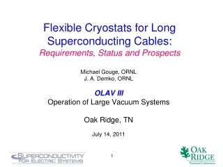
Flexible Cryostats for Long Superconducting Cables:Requirements, Status and Prospects Michael Gouge, ORNL J. A. Demko, ORNL OLAV III Operation of Large Vacuum Systems Oak Ridge, TN July 14, 2011 1
Utility Customer Perspective: Underground Cables • Utility perspective: “bury and forget” cable/cryostat for 20-30 years. • HTS Cables, with an advantage of 3-5 times higher cable current density relative to conventional copper cables, require an active cryogenic cooling system and an effective vacuum thermal insulation that is transparent to the utility company. • From a conventional dc cable brochure: HVDC Light (ABB) - Invisible power transmission 2
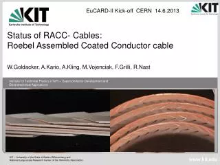
Typical Cable Cryostat Installations High-temperature superconducting cable configurations: a) Columbus, OH 3-phase HTS “tri-axial” cable going into the cryostat; b) “Three-in-one” Albany, NY HTS cable in the cryostat; c) Long Island, NY cable showing single phase in one of 3 parallel, separate cryostats. a) a) b) c) 3
Cable Flexible Cryostat Goals Cable flexible cryostat on a reel with a leak test in progress (images courtesy of Nexans). 4
Cryostat Configuration Options • Constraints: • Need pump-out port every ~100-m for initial bake-out/evacuation • Need over-pressure protection on each discrete vacuum section (CGA standards) • Loss of a single 100-m section may shutdown cable as increase in heat load of order kW’s at 77 K may challenge the cryogenic system (as well as skewed cable temperatures) • Option 1: Discrete 100-m vacuum sections along cable • Pros: easier to test at factory, easier to locate leak in service (if you have access to 100-m sections) • Cons: Single failure may take cable out of service; difficult to pump if underground 100-m section has a leak • Option 2: 100-m sections tied together in a single vacuum volume • Pros: Over-pressure protection easier (devices at one or both ends), can monitor entire vacuum region, can pump on ends if underground 100-m section has leak (but may be ineffective) • Cons: Single failure takes the cable out of service for certain HTS conductor temperature and liquid nitrogen pressure distributions for a kilometer-long HTS cable with and without a damaged 100-m cryostat section. The inlet liquid nitrogen flow, pressure, and temperature are 200 g/s, 10 bar, and 65 K, respectively. 5
General Design Guidelines (1) • Since reliability is proportional to (length)-1 and a single phase failure will shutdown the other 2 electrical phases: • put 3 phases in one cryostat instead of 1 phase per cryostat • LN counter-flow should be considered rather than a separate nitrogen return cryostat • Since running with even one 100-m section with poor vacuum may not be possible (cable temperature profile and increased heat load) • Use common vacuum for multiple 100-m sections • Simplifies over-pressure relief and vacuum monitoring (only at ends) • Allow for movement on cool-down and warm-up and increased heat loads in cable bends. Images of the behavior of the 500-m CRIEPI/Furukawa cable in the offset section. (a) Cool-down; (b) Warm-up. From M. Ichikawa et al., IEEE Trans. Applied Superconductivity, 15, No. 2, 2005. 6
General Design Guidelines (2) • Burst disks are more reliable than relief valves • But more difficult to recover from an overpressure event or leak • Consider tee section with a 3-way valve and 2 burst disks so recovery is simplified • Invest on front end in long life, distributed getters as getter replacement or mechanical pumping every 100-m may not be practical. • Pumping only at ends not effective for a common vacuum length > 200-300 m • Pumping in mid-sections requires blanked-off pumping port with snorkel valve every 100-m and local 208/480 V power for pumps. • A major leak in the middle of a cable run will overwhelm getters/pumps • How likely is this event? Not much data on reliability of long flexible cryostat sections for extended times 7
Cryostat Reliability Issues • Loss of vacuum integrity during or just after manufacture • before or after initial cool-down • due to incorrect or poor quality materials and/or weld process control • example: Pirelli Cable Project. In 2 of 3 electrical phases: • Several micro-cracks detected in inner corrugated tube(s) • All micro-cracks oriented parallel to the tube longitudinal axis and inside a corrugation groove near the weld line. • No corporate experience with manufacture of flexible vacuum cryostats (as opposed to flexible tubes operating at ambient temperature) Crack detail on outer surface Crack detail on inner surface 8
Pirelli Conclusions(Jim Curley, Pirelli, 2003 DOE Peer Review) • Conclusions • SEM analysis suggests defects formed during the solidification process. • Material characteristics contributed to defects rather than solely welding process anomalies. • Hypothesis that excessive gaseous content (H2) may have contributed to defects. • Resulted in hydrogen embrittlement; incombination with cold working in the corrugation process had a significant role in the creation of local weak spots. • Weak spots may have turned into complete fractures upon further mechanical stress of installation. This type of early vacuum integrity failure can be avoided by fully qualified manufacturing processes (materials and welds), quality control and warm and cold testing. 9
Installation Recessed port for pump-down, no relief capability • Cable Cryostat Installation • Damage on installation of cryostat in duct – • recessed pump-out ports every 100-m and burst disks on ends only to minimize damage during pulling of cryostat into cable duct • Damage during pulling of cable in cryostat • If cable not made in parallel with cryostat • Concern in both cases: generation of small, (cold) leak from rough handling, friction • In principle, cryostat can be tested before cable is energized • internal pressure test at 10-20 bar and vacuum jacket test to verify 10-5-10-6 torr cold). • But access may be difficult for long runs Provided by Nexans-Cryoflex 10
Getters for passive pumping • The LN2 cryogen flowing in the inner corrugated pipe can effectively pump any water vapor or air from small leaks. • Hydrogen from out-gassing and permeation is not pumped by the 70-77 K inner wall. Hydrogen molecules can outgas from the stainless steel, the MLI and the plastic-like spacer material that separates the inner and outer corrugated piping. • Hydrogen has to be removed by chemical pumping of the getter material(s). • The ideal positioning of getter material is to distribute it along the 100-m cryostat sections (for instance a getter container each 10 m). • Conductance limitations are not a serious issue in this application given the long times involved in sorption dynamics 11
Getters for passive pumping (cont.) • The outgassing behavior of cryostat materials can be predicted using literature data or by actual laboratory tests. The total amount of gas released during cryostat lifetime is obtained by integration of the formula: Q(t)= Q0 t -a where Q0is the out-gassing rate after 1 hr. • The data for each gas, and for each material used inside the cryostat is extrapolated to 20 years by fitting of the outgassing rate curve of the first 24-100 hours that determines the specific value of the parameters Q0and a. • Data obtained in past tests indicate that a quantity of the above getter material around 300 grams for each 100 meters should be sufficient for 20+ years lifetime Input by Livio Rosai, SAES 12
Outgassing and Getter Lifetimes The net (outgassing – getter pumping) rate and the time to go from an initial internal cryostat pressure of 1.33 x 10⁻⁴ Pa (10-6 torr) to a final pressure of 0.133 Pa (10-3 torr) (diamond symbols). These two curves show the approximate getter lifetime: the vertical axis is now the getter pumping rate and the lifetime is estimated for a PdO getter with a mass of 100 g (circle symbols) and 500 g (square symbols) 13
Options for leak or saturated getter in service • If the getter is well dimensioned it should last for the lifetime of the cryostat. • It is not practical to replace getters when the cable is cold. • Warm replacement requires several weeks for warm-up, getter installation, baking and pump-down and cool-down). • Option to use mechanical pumps on each end when getters are saturated (need internal vacuum < 10-4 torr), may not be practical due to complexity and high cost. • Ineffective in mid-section for long cable runs Input by Livio Rosai, SAES 14
How can R&D and ingenuity improve the situation? • Improved and distributed getters for 10-20 service lifetime (SAES input) • Low out-gassing internal supports and MLI • New material that has 1/3 to 1/6 the thermal conductivity of standard MLI for degraded vacuum of 1 torr • developed by NASA KSC • Layered composite (LCI) performs better than standard multi-layer insulation systems if vacuum degrades. • How can longitudinal weld and vacuum accessory reliability be improved by 1-2 orders of magnitude over historical data? NASA LCI: Fesmire et al. CEC/ICMC 2001 15
Extra slides Research sponsored by the U.S. Department of Energy – Office of Electricity Delivery and Energy Reliability, Superconductivity Program for Electric Power Systems 16
Test a cryostat for extended periods • Albany cable project is monitoring the 350-m return cryostat for long-term vacuum maintenance • leak rate < 10-10 Pa-m3/s • inner wall is not cold like it would be in service 17
R. Bunde et al., “Reliability of Welds and Brazed Joints in Blankets and Its Influence on Availability,” Fusion Eng. Design, 16, 59-72 (1991). 18
Cryostat Cost Considerations • Cable now $6,000/m, future $500/m with tape $10/kA-m • Assume 3 phases in one cryostat, 3 kA phase current, run at 50% of Ic, cold dielectric with HTS shield • Cryostat now $650/m, near-term $500/m, future $300-$400/m • At $10/kA-m tape cost, the cryostat is almost as much as the cable cost per meter • Vacuum pumping $10K/100 m = $100/m • If vacuum pumping is included the cryostat cost and cable cost are about the same! • Long life (passive) getters less expensive • 3-f power, enclosure and maintenance for pumps problematic 19