Download
1 / 38
380 likes | 494 Views
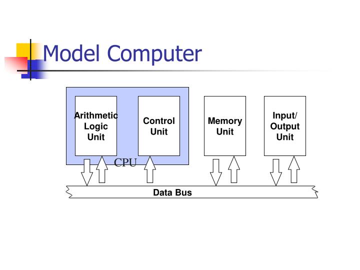
Model Computer. Arithmetic Logic Unit. Control Unit. Memory Unit. Input/ Output Unit. CPU. Data Bus. Control Unit. MAR. Instruction Decoder. PC. Arithmetic Logic Unit. Memory Unit. Input/ Output Unit. IR. Memory Unit. Address Decoder. MAR. Main Store. Arithmetic

E N D
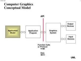
Model Computer Arithmetic Logic Unit Control Unit Memory Unit Input/ Output Unit CPU Data Bus
Control Unit MAR Instruction Decoder PC Arithmetic Logic Unit Memory Unit Input/ Output Unit IR
Memory Unit Address Decoder MAR Main Store Arithmetic Logic Unit Control Unit Input/ Output Unit MDR
Arithmetic/Logic Unit Control Unit Main Memory Input/ Output Unit SR ACC
Model Computer Address Decoder MAR Instruction Decoder PC SR ACC IR MDR
Registers • A register is a single storage unit where data is stored temporary for a special purpose • MAR holds the address of the memory location to be accessed • MDR holds the data item read from or written to the specified memory location
Registers • PC holds the address of the next instruction to be fetched from the main store • IR holds the current instruction fetched from the main store while it is being decoded
Registers • ACC holds the data item to be processed or the results of the most recent operations in the ALU • SR holds a set of condition flags which describe the status of the most recent operation carried out by the ALU
Programming the CPU • 00001 : Load the contents in memory location 11111 into the accumulator • 00010 : Store the contents in the accumulator in the memory location 11101
PC is set to 00001 initially MAR is loaded with 00001 Fetch Cycle 00111111 00001 01011110 1 00001 01000001
Address decoder selects the memory location 00001 Fetch Cycle 2 00111111 00001 01011110 1 00001 01000001
The instruction in location 00001 is loaded into MDR Fetch Cycle 2 00111111 00001 01011110 1 00001 3 01000001 00111111
The instruction is then copied to IR Fetch Cycle 2 00111111 00001 01011110 1 00001 3 01000001 00111111 00111111 4
PC is set to 00010 The instruction is decoded Execution Cycle 00111111 00001 LDA 01011110 5 00010 01000001 00111111
MAR is set to 11111 Execution Cycle 00111111 11111 LDA 01011110 6 5 00010 01000001 00111111
The address decoder selects the location 11111 Execution Cycle 7 00111111 11111 LDA 01011110 6 5 00010 01000001 00111111
The data in location 11111 is loaded into MDR Execution Cycle 7 00111111 11111 LDA 01011110 6 5 00010 01000001 00111111 8 01000001
The data is then copied to ACC Execution Cycle 7 00111111 11111 LDA 01011110 6 5 00010 01000001 01000001 00111111 8 01000001 9
Fetch Cycle 00111111 00010 01011110 1 00010 01000001 01000001
Fetch Cycle 2 00111111 00010 01011110 1 00010 01000001 01000001
Fetch Cycle 2 00111111 00010 01011110 1 00010 3 01000001 01000001 01011110
Fetch Cycle 2 00111111 00010 01011110 1 00010 3 01000001 01000001 01011110 01011110 4
Execution Cycle 00111111 00010 STA 01011110 5 00011 01000001 01000001 01011110 00111110
Execution Cycle 00111111 11110 STA 01011110 6 5 00011 01000001 01000001 01011110 00111110
Execution Cycle MAR 7 00111111 11110 STA 01011110 6 5 00011 PC 01000001 01000001 01011110 01000001
Execution Cycle 7 00111111 11110 STA 01011110 6 5 00011 01000001 01000001 01011110 01000001 8
Execution Cycle 8 00111111 11110 STA 01011110 6 5 00011 01000001 01000001 01000001 01011110 9 01000001 7
SMC Instruction Set LDA load accumulator with memory STA store accumulator in memory ADD add memory to accumulator SUB subtract memory from accumulator DEC decrement memory by 1 JMP unconditional jump BNE branch if negative STP stop
SMC Instruction Set LDA LoaDAccumulator with memory STA STore Accumulator in memory ADD ADD memory to accumulator SUB SUBtract memory from accumulator DEC DECrement memory by 1 JMP unconditional JuMP BNE Branch if NEgative STP SToP
Fetch/Execution Cycle • Address in PC is sent to MAR • Address decoder interpret the address in MAR and locate the specified memory location • Control signal ( read ) is issued • Contents in specified location are deposited into MDR • Contents is then sent to IR • Execute the instruction held in IR
Example program #1 Address Instruction 1 00001 LDA 11111 00010 ADD 11110 00011 STA 11101 00100 STP 2 3 4
Example program #2 Address Instruction 1 00001 LDA 11111 00010 SUB 11110 00011 BNE 00110 00100 LDA 11111 00101 JMP 00111 00110 LDA 11110 00111 STA 11101 01000 STP 2 3 4 5 6 7 8
00000001(01) 00000010(02) 00000011(03) 00000100(04) 00000101(05) 00000110(06) … … … 10000001(81) 10000010(82) 10000011(83) 10000100(84) Memory Allocation Each instr. consists of 2 bytes Address(hex.) Main Memory 00000000 Program starts at 00000011 00000000 LDA 10010110 10000011 83 Program area 01101000 ADD 10000010 82 LDA 83 ADD 82 … … … … … 00110011 00000000 Data area 01010001 01100010
Addressing Mode • Immediate mode • The actual operand is the data included in the instr. • Direct mode • The actual operand is in the location(in MM) specified in the instr.
Instruction Types • Register-Memory move • (LDA) move data from memory location to register (usually the accumulator) • (STA) move data from register to mem. Location • Arithmetic operation • (ADA) add content in location to register • (SUB) subtract content in location from register • (INC) increment (+1) content in mem. or reg. • (DEC) decrement (-1) content in mem. or reg.
Instruction Type • Branch instruction • (JMP) unconditional jump – jump to location specified • (JPN) conditional jump – jump to location specified IF the content in acc. is negative (i.e. the N bit in SR is ‘1’) • (JPZ) conditional jump - jump to location specified IF the content in acc. is zero (i.e. the Z bit in SR is ‘1’) • Input/output instruction • (INP) input – reads in data (and store in mem. loc. or acc.) from data stream in input device • (OUT) output – prints out data (in mem. loc. or acc.) to output device • Terminate execution (STP) stop – terminate execution of program
If ..then..else.. If a=0 then b:=b+1 Else c:=c+1 LDA A JPZ ZERO LDA C ADD #1 STA C JMP CONT ZERO: LDA B ADD #1 STA B CONT: OUT …
LOOP e.g. REPEAT A=A-1 UNTIL A<0 LOOP: LDA A JPN CONT SUB #1 STA A JMP LOOP CONT: …